UMSITRPDS3-1
Appendix C - Elevation and Suppression Corrections
November 2010
13-1
13.0 APPENDIX C - ELEVATION AND SUPPRESSION CORRECTIONS
When installing a transmitter to measure liquid level, configuration of the Sensor Input Block often must
include an adjustment for one of two conditions introduced by the mounting arrangement:
•
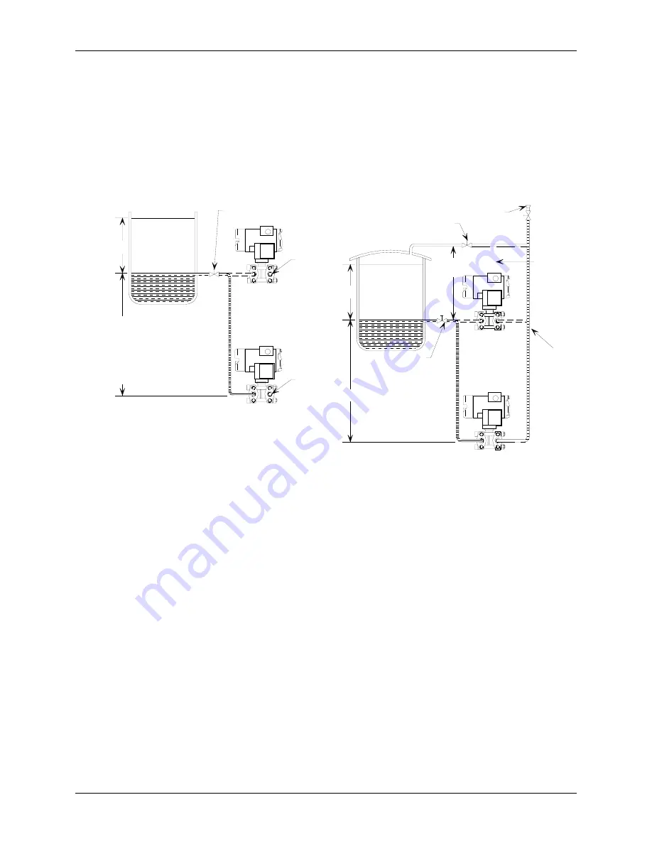
Elevated Span - The Lower Range Value (LRV) of the transmitter needs to be configured
above “0.” See Figure C-1.
•
Suppressed Span - The LRV of the transmitter needs to be configured below “0.” See
Figure C-2.
Max. Range
Min. Range
HP Shut-Off
Valve
LP
HP
Vent
Span
Elevated Span: To
calculate maximum
distance, subtract
actual span setting
from range limit given
in specification.
Vent
MG00363b
Fill Connection
See
Section 9
Specifi-
cations
for range
limit.
LP line
filled with
condensate
Max. Range
Min. Range
LP Shut-Off
Valve
HP Shut-Off
Valve
LP
HP
Span
Distance X
Suppressed
Span
MG00363b
A. Elevated Span
B. Suppressed Span
FIGURE 13-1 Elevation and Suppression Examples
A brief discussion of how to make adjustments for elevation and suppression follows. Then two examples
of the calculations needed to determine configuration parameters are given. Finally, a brief procedure that
does not involve calculations is provided.
13.1 HOW ADJUSTMENT IS MADE
Because the transmitter can handle elevation and suppression simply by setting parameters, it is not
necessary to introduce mechanical measures, such as installing piping backwards or adding additional
hardware.
The range of the transmitter can be set anywhere, forward or reverse acting, as long as the following
criteria are met:
LRL
≤
LRV
≤
URL
LRL
≤
URV
≤
URL
Span = [URV - LRV]
≥
Min Span
Содержание 7MF4033 series
Страница 48: ...Model 275 Universal Hart Communicator UMSITRPDS3 1 November 2010 2 26 ...
Страница 86: ...Installation UMSITRPDS3 1 November 2010 4 34 ...
Страница 152: ...Calibration and Maintenance UMSITRPSD3 1 November 2010 7 20 ...
Страница 158: ...Circuit Description UMSITRPDS3 1 November 2010 8 6 ...
Страница 197: ......
Страница 198: ......
Страница 200: ...Model Designations and Specifications UMSITRPDS3 1 November 2010 9 42 ...
Страница 204: ...Glossary UMSITRPDS3 1 November 2010 10 4 ...
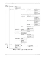
Страница 208: ...Appendix A Online Configuration Map UMSITRPDS3 1 11 4 November 2010 ...
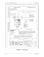
Страница 210: ...Appendix B Hazardous Area Installation UMSITRPDS3 1 12 2 November 2010 FIGURE 12 1 Control Drawing ...
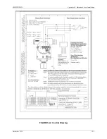
Страница 211: ...UMSITRPDS3 1 Appendix B Hazardous Area Installation November 2010 12 3 FIGURE 12 2 Control Drawing ...
Страница 212: ...Appendix B Hazardous Area Installation UMSITRPDS3 1 12 4 November 2010 FIGURE 12 3 Control Drawing ...
Страница 216: ...Appendix C Elevation and Suppression Correction UMSITRPDS3 1 13 4 November 2010 ...


