UMSITRAPDS3-1
Model Designations and Specifications
November 2010
9-37
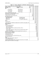
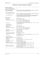
TABLE 9-20 Certificate and Approvals, All Models
Certificate and approvals
Classification according to pressure
equipment directive (DRGL 97/23/EC)
• Models 7MF4033, 7MF4233,
7MF4333, and 7MF4633
For gasses of liquid group 1 and liquids of fluid group 1; complies with requirements
of Article 3, paragraph 3 (sound engineering practices)
• Models 7MF4433 and 7MF4533
- PN 32/160 (MWP 464/ 2320 psi)
For gasses of liquid group 1 and liquids of fluid group 1; complies with requirements
of Article 3, paragraph 3 (sound engineering practices)
- PN 420 (MWP 6092 psi)
For gasses of liquid group 1 and liquids of fluid group 1; complies with basic safety
requirements of Article 3, paragraph 1 (appendix 1); assigned to category III,
conformity evaluation module H by the TUV Nord.
Explosion protection
• Intrinsic safety “i”
PTB 99 ATEX 2122
- Identification
Ex II 1/2 G EEx ia/ib IIB/IIC T6
- Permissible ambient temperature
-40 to +85°C (-40 to +185°F) temperature class T4
-40 to +70°C (-40 to +158°F) temperature class T5
-40 to +60°C (-40 to +140°F) temperature class T6
- Connection
To certified intrinsically-safe circuits with maximum values: Ui = 30V, Ii = 100 mA,
Pi = 750 mW; Ri = 300
Ω
- Effective internal
inductance/capacitance
Li = 0.4 mH, Ci = 6 nF
• Explosion Proof “d”
PTB 99 ATEX 1160
- Identification
Ex II 1/2 G EEx d IIC T4/T6
- Permissible ambient temperature
-40 to +85°C (-40 to +185°F) temperature class T4
-40 to +60°C (-40 to +140°F) temperature class T6
- Connection
To circuits with values: U
H
= 10.5 to 45 Vdc
• Dust explosion protection, Zone 20
PTB 01 ATEX 2055
- Identification
Ex II 1 D IP65 T 120°C
Ex II 1/2 D IP65 T 120°C
- Permissible ambient temperature
-40 to +85°C (-40 to +185°F)
- Surface temperature, maximum
120°C (248°F)
- Connection
To certified intrinsically-safe circuits with maximum values: Ui = 30V, Ii = 100 mA,
Pi = 750 mW, Ri = 300
Ω
- Effective internal
inductance/capacitance
Li = 0.4 mH, Ci = 6 nf
• Dust explosion protection, Zone 21/22
PTB 01 ATEX 2055
- Identification
Ex II 2 D IP65 T 120°C
- Connection
To circuits with values: U
H
= 10.5 to 45 Vdc; P max =1.2W
• Type of protection “n”, Zone 2
TUV 01 ATEX 1696 X
- Identification
Ex II 3 G EEx nA L IIC T4/T5/T6
• Explosion protection to FM
Certificate of Compliance 3008490
- Identification (XP/DIP) or (IS); (NI)
CL 1, DIV 1, GP ABCD T4/T5/T6; CLII, DIV 1, GP EFG; CL III;
CL I, ZN 0/1 AEx ia IIC T4/T5/T6;
CL 1, DIV 2, GP ABCD T4/T5/T6; CL II, DIV 2, GP FG; CL III
• Explosion protection to CSA
Certificate of Compliance 1153651
- Identification (XP/DIP) or (IS)
CL 1, DIV 1, GP ABCD T4/T5/T6; CLII, DIV 1, GP EFG; CL III;
Ex ia IIC T4/T5/T6;
CL 1, DIV 2, GP ABCD T4/T5/T6; CL II, DIV 2, GP FG; CL III
Содержание 7MF4033 series
Страница 48: ...Model 275 Universal Hart Communicator UMSITRPDS3 1 November 2010 2 26 ...
Страница 86: ...Installation UMSITRPDS3 1 November 2010 4 34 ...
Страница 152: ...Calibration and Maintenance UMSITRPSD3 1 November 2010 7 20 ...
Страница 158: ...Circuit Description UMSITRPDS3 1 November 2010 8 6 ...
Страница 197: ......
Страница 198: ......
Страница 200: ...Model Designations and Specifications UMSITRPDS3 1 November 2010 9 42 ...
Страница 204: ...Glossary UMSITRPDS3 1 November 2010 10 4 ...
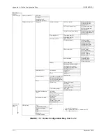
Страница 208: ...Appendix A Online Configuration Map UMSITRPDS3 1 11 4 November 2010 ...
Страница 210: ...Appendix B Hazardous Area Installation UMSITRPDS3 1 12 2 November 2010 FIGURE 12 1 Control Drawing ...
Страница 211: ...UMSITRPDS3 1 Appendix B Hazardous Area Installation November 2010 12 3 FIGURE 12 2 Control Drawing ...
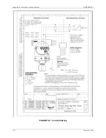
Страница 212: ...Appendix B Hazardous Area Installation UMSITRPDS3 1 12 4 November 2010 FIGURE 12 3 Control Drawing ...
Страница 216: ...Appendix C Elevation and Suppression Correction UMSITRPDS3 1 13 4 November 2010 ...


