UMSITRPDS3-1
Pre-Installation Test
November 2010
3-3
3.2 ESTABLISHING COMMUNICATION
1.
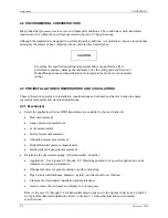
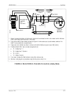
Connect the transmitter, power supply, and HART Communicator in a loop.
2.
Apply power to the transmitter.
3.
Press the HART Communicator’s I/O key. The first display
is the Online menu (at right). Appropriate values for pressure
and device type should be displayed.
4.
If the Online menu does not appear, or if a “Device not
found” message displays, check connections and power
source and repeat the above steps.
3.3 TESTING THE TRANSMITTER
Although a transmitter continuously performs an on-line self-
test, a more extensive self-test can be performed when
communication with the HART Communicator has been
established.
1.
In the Online menu, choose option 3 Device setup, then press 2 Diag/Service, and finally press 2
Simulation/Test.
2.
In the Simulation/Test menu, choose option 2 Test and then
press1 Self test or press the RIGHT ARROW/SELECT key
to start the test.
3.
The transmitter performs the self-test.
•
If testing is successful, the message “Self test OK” appears and the Communicator returns to the
Test menu.
•
If testing fails, the message “Transmitter FAILED the
transmitter selftest” displays, and the transmitter goes to
the prescribed failsafe condition. Refer to Section 7
Calibration and Maintenance to troubleshoot the
transmitter.
4.
Press the HOME softkey to return to the Online menu.
SITRANS P
Online
"
1->Press
2 Type
3 Device Setup
HELP |SAVE
Note: If using a Model 375 Field
Communicator, see the inside of
the front cover of this manual.
Содержание 7MF4033 series
Страница 48: ...Model 275 Universal Hart Communicator UMSITRPDS3 1 November 2010 2 26 ...
Страница 86: ...Installation UMSITRPDS3 1 November 2010 4 34 ...
Страница 152: ...Calibration and Maintenance UMSITRPSD3 1 November 2010 7 20 ...
Страница 158: ...Circuit Description UMSITRPDS3 1 November 2010 8 6 ...
Страница 197: ......
Страница 198: ......
Страница 200: ...Model Designations and Specifications UMSITRPDS3 1 November 2010 9 42 ...
Страница 204: ...Glossary UMSITRPDS3 1 November 2010 10 4 ...
Страница 208: ...Appendix A Online Configuration Map UMSITRPDS3 1 11 4 November 2010 ...
Страница 210: ...Appendix B Hazardous Area Installation UMSITRPDS3 1 12 2 November 2010 FIGURE 12 1 Control Drawing ...
Страница 211: ...UMSITRPDS3 1 Appendix B Hazardous Area Installation November 2010 12 3 FIGURE 12 2 Control Drawing ...
Страница 212: ...Appendix B Hazardous Area Installation UMSITRPDS3 1 12 4 November 2010 FIGURE 12 3 Control Drawing ...
Страница 216: ...Appendix C Elevation and Suppression Correction UMSITRPDS3 1 13 4 November 2010 ...


