On-Line Operation
UMSITRPDS3-1
November
2010
6-34
4.
In the Simulation Test menu, press 1 Simulation to display the Select menu. Choose one of the
following.
1 Loop Test: To test the loop, press 1. A warning message will appear: “Loop should be removed
from automatic control.” Press OK to continue. Then select either 4 ma, 20 mA, or a user-
entered value and press ENTER. Select End or ABORT to exit and return to the previous
menu. Press OK to return to the previous menu with the selected current sustained. To end
the simulation, press either 4 End or ABORT and return to the previous menu.
2 Inputs: From the menu that appears, select the pressure and/or temperature to be simulated.
Pressure simulation can employ either a fixed value or ramped values (specify starting value,
end value, step duration, and number of steps). Follow the on-screen prompts. End the
simulation and return to the previous menu by pressing ABORT.
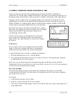
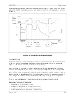
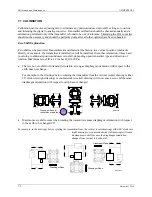
FIGURE 6-7 Simulation Circuit Diagram
6.4.21 Self Test and Master Reset
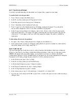
A transmitter self test or master reset can be initiated from the HART Communicator.
1.
In the Online menu, press 3 Device Setup. In the Device Setup menu, press 2 Diagnostics/Service.
2.
In the Diagnostics/Service menu, press 2 Simulation Test. In the Simulation/Test menu, press 2 Test
3.
In the Test menu, press 1 Self Test to direct the transmitter to perform a self test of its internal
circuitry or press 2 Master Reset to direct the transmitter to reset its internal circuitry. Follow the on-
screen prompts. “Init” will momentarily flash in the display.
!
Содержание 7MF4033 series
Страница 48: ...Model 275 Universal Hart Communicator UMSITRPDS3 1 November 2010 2 26 ...
Страница 86: ...Installation UMSITRPDS3 1 November 2010 4 34 ...
Страница 152: ...Calibration and Maintenance UMSITRPSD3 1 November 2010 7 20 ...
Страница 158: ...Circuit Description UMSITRPDS3 1 November 2010 8 6 ...
Страница 197: ......
Страница 198: ......
Страница 200: ...Model Designations and Specifications UMSITRPDS3 1 November 2010 9 42 ...
Страница 204: ...Glossary UMSITRPDS3 1 November 2010 10 4 ...
Страница 208: ...Appendix A Online Configuration Map UMSITRPDS3 1 11 4 November 2010 ...
Страница 210: ...Appendix B Hazardous Area Installation UMSITRPDS3 1 12 2 November 2010 FIGURE 12 1 Control Drawing ...
Страница 211: ...UMSITRPDS3 1 Appendix B Hazardous Area Installation November 2010 12 3 FIGURE 12 2 Control Drawing ...
Страница 212: ...Appendix B Hazardous Area Installation UMSITRPDS3 1 12 4 November 2010 FIGURE 12 3 Control Drawing ...
Страница 216: ...Appendix C Elevation and Suppression Correction UMSITRPDS3 1 13 4 November 2010 ...

