Model 275 Universal Hart Communicator
UMSITRPDS3-1
November
2010
2-14
5.
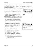
With the Blank Template menu displayed, choose from the
options available, as follows:
Mark All
– Flags (selects) all configurable variables for
sending to a connected HART-compatible device.
Unmark All
– Remove the flags from all configurable
variables in the configuration. Unmarked configuration
variables are not sent to a connected device.
Edit Individually
– Open the Edit individually menu (at
right).
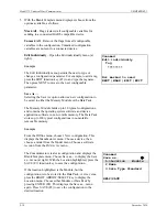
Example
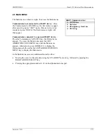
The Edit individually menu permits the user to type or
change a configuration parameter. For example, to add a tag,
press the EDIT function key (F3) to and type the tagname.
Then press NEXT to move to the next configurable
parameter.
Save As. . .
Selecting the Save As option allows a new configuration to
be saved to either the Memory Module or the Data Pack.
The Memory Module holds up to 10 typical configurations,
and contains the operating system software and device
application software in non-volatile memory. The Data Pack
stores up to 100 typical configurations in nonvolatile,
removable memory.
Example
From the Offline menu, choose 1 New configuration. This
displays the Manufacturer menu. Choose a device, then
choose a model from the Model menu. Choose a software
revision from the Fld dev rev menu.
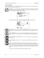
The Communicator creates a configuration and displays the
Blank Template menu. Choose Save as... to display the Save
as... menu (at right). With the Location highlighted, press the
SAVE (F2) function key to save the configuration.
If the location highlighted is the Module, but the
configuration is to be stored in the Data Pack, or vice versa,
press the RIGHT ARROW/SELECT key to display the
Location menu. Choose either Module or Data Pack by
pressing ENTER (F4). This displays the Save as... menu
again. Press SAVE (F2) to save the configuration in the
desired location.
Unnamed
Save as...
"
1->Location Module
2 Name
3 Data Type Standard
HELP|SAVE
Unnamed
Edit individually
Tag
********
Not marked to send
NEXT |MARK |EDIT |EXIT
Содержание 7MF4033 series
Страница 48: ...Model 275 Universal Hart Communicator UMSITRPDS3 1 November 2010 2 26 ...
Страница 86: ...Installation UMSITRPDS3 1 November 2010 4 34 ...
Страница 152: ...Calibration and Maintenance UMSITRPSD3 1 November 2010 7 20 ...
Страница 158: ...Circuit Description UMSITRPDS3 1 November 2010 8 6 ...
Страница 197: ......
Страница 198: ......
Страница 200: ...Model Designations and Specifications UMSITRPDS3 1 November 2010 9 42 ...
Страница 204: ...Glossary UMSITRPDS3 1 November 2010 10 4 ...
Страница 208: ...Appendix A Online Configuration Map UMSITRPDS3 1 11 4 November 2010 ...
Страница 210: ...Appendix B Hazardous Area Installation UMSITRPDS3 1 12 2 November 2010 FIGURE 12 1 Control Drawing ...
Страница 211: ...UMSITRPDS3 1 Appendix B Hazardous Area Installation November 2010 12 3 FIGURE 12 2 Control Drawing ...
Страница 212: ...Appendix B Hazardous Area Installation UMSITRPDS3 1 12 4 November 2010 FIGURE 12 3 Control Drawing ...
Страница 216: ...Appendix C Elevation and Suppression Correction UMSITRPDS3 1 13 4 November 2010 ...

