UMSITRPDS3-1
Installation
November 2010
4-27
4.5 MECHANICAL INSTALLATION, All Models
The following subsections describe rotating the enclosure housing relative to the measuring cell to clear
obstructions or view the optional display, orienting the display for ease of reading, and installing
electrical conduit and cables.
4.5.1 Enclosure Rotation
1.
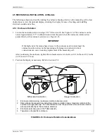
Loosen the enclosure setscrew using a 3/32" Allen wrench. See Figure 4-14. The enclosure can be
rotated approximately 135º in either direction from the point where the enclosure rotation arrow
points directly at the enclosure setscrew; see Figure 4-14.
IMPORTANT
If the high end of the ramp-shaped recess in the enclosure neck is rotated past the
enclosure rotation arrow on the measuring cell, damage to internal electrical
connections can occur, requiring replacement of the measuring cell.
After positioning the enclosure, tighten the enclosure setscrew to between 30.1 in-lbs and 31.9 in-lbs
(3.4 N-m and 3.6 N-m).
2.
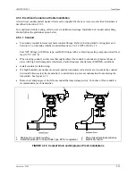
Position the display as necessary. Refer to Section 4.5.2.
MG
00353a
Differential Construction
Gauge Construction
1
2
3
4
1
2
3
4
Enclosure rotation arrow (enclosure rotation reference point)
Ramp-shaped recessed area indicating enclosure rotation range; maximum rotation of the
enclosure is approximately 135º either direction from the point where the enclosure rotation
arrow points directly at the enclosure setscrew.
Enclosure setscrew (use a 3/32" Allen wrench)
Tag plate on transmitter enclosure
FIGURE 4-14 Enclosure Rotation Considerations
Содержание 7MF4033 series
Страница 48: ...Model 275 Universal Hart Communicator UMSITRPDS3 1 November 2010 2 26 ...
Страница 86: ...Installation UMSITRPDS3 1 November 2010 4 34 ...
Страница 152: ...Calibration and Maintenance UMSITRPSD3 1 November 2010 7 20 ...
Страница 158: ...Circuit Description UMSITRPDS3 1 November 2010 8 6 ...
Страница 197: ......
Страница 198: ......
Страница 200: ...Model Designations and Specifications UMSITRPDS3 1 November 2010 9 42 ...
Страница 204: ...Glossary UMSITRPDS3 1 November 2010 10 4 ...
Страница 208: ...Appendix A Online Configuration Map UMSITRPDS3 1 11 4 November 2010 ...
Страница 210: ...Appendix B Hazardous Area Installation UMSITRPDS3 1 12 2 November 2010 FIGURE 12 1 Control Drawing ...
Страница 211: ...UMSITRPDS3 1 Appendix B Hazardous Area Installation November 2010 12 3 FIGURE 12 2 Control Drawing ...
Страница 212: ...Appendix B Hazardous Area Installation UMSITRPDS3 1 12 4 November 2010 FIGURE 12 3 Control Drawing ...
Страница 216: ...Appendix C Elevation and Suppression Correction UMSITRPDS3 1 13 4 November 2010 ...

