Model Designations and Specifications
UMSITRPDS3-1
November
2010
9-20
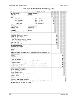
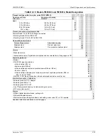
TABLE 9-8 Model 7MF4533, Model Designation
Differential pressure and flow transmitter, two-wire, series DSIII, Model 7MF4533-
-
Measuring cell filling
Silicon oil
Measuring cell cleaning
Standard
1
Span
2.5 to 250 mbar
(1.004 to 100.4 InH
2
O)
D
6 to 600 mbar
(2.409 to 240.9 InH
2
O)
E
16 to 1600 mbar
(6.424 to 642.4 InH
2
O)
F
50 to 5000 mbar
(20.08 to 2008 InH
2
O)
G
0.3 to 30 bar
(4.35 to 435 psi)
H
Wetted parts materials (stainless steel process flanges)
Seal diaphragm
Parts of the measuring cell
Stainless steel
Stainless steel
A
Hastelloy
Stainless steel
B
Gold
Gold
L
Process connection
Female thread 1/4-18 NPT with flange connection
•
Sealing screw opposite process connection:
- Mounting thread M12 to DIN 19213
1
- Mounting thread 7/16-20 UNF to EN 61518
3
•
Venting on side of process flanges.
- Mounting thread M12 to DIN 19213
5
- Mounting thread 7/16-20 UNF to EN 61518
7
Non-wetted parts materials
Process flange screws Electronics
housing
Stainless steel
Die-cast aluminum
2
Stainless steel
Stainless steel precision casting
3
Version
•
Standard version
1
•
International version, English label inscriptions and documentation in 5 languages on CD
2
Explosion protection
•
Without
A
•
With ATEX, type of protection:
Intrinsic safety (EEx ia)
B
Explosion proof (EEx d)
D
Intrinsic safety and explosion-proof enclosure (EEx ia + EEx d)
P
Ex nA/nL (Zone 2)
E
Intrinsic safety, explosion-proof enclosure and dust explosion protection (EEx ia +
EEx d + Zone 1D/2D)
R
•
With FM + CSA, type of protection: Intrinsic safety and explosion proof (is + xp) PN 360 maximum
N C
Electrical connection / cable entry
•
Screwed gland PG 13.5; Adapter
A
•
Screwed gland M20 x 1.5
B
•
Screwed gland 1/2-14 NPT
C
•
Han 7D plug (plastic housing) includes mating connector
D
•
M12 connector (metal)
F
Display
•
Without (digital indicator hidden, setting: mA)
1
•
With visible digital indicator
6
•
With customer specific digital indicator and setting; Order code Y21 or Y22 required.
7
Additional selections and data on next page.
Содержание 7MF4033 series
Страница 48: ...Model 275 Universal Hart Communicator UMSITRPDS3 1 November 2010 2 26 ...
Страница 86: ...Installation UMSITRPDS3 1 November 2010 4 34 ...
Страница 152: ...Calibration and Maintenance UMSITRPSD3 1 November 2010 7 20 ...
Страница 158: ...Circuit Description UMSITRPDS3 1 November 2010 8 6 ...
Страница 197: ......
Страница 198: ......
Страница 200: ...Model Designations and Specifications UMSITRPDS3 1 November 2010 9 42 ...
Страница 204: ...Glossary UMSITRPDS3 1 November 2010 10 4 ...
Страница 208: ...Appendix A Online Configuration Map UMSITRPDS3 1 11 4 November 2010 ...
Страница 210: ...Appendix B Hazardous Area Installation UMSITRPDS3 1 12 2 November 2010 FIGURE 12 1 Control Drawing ...
Страница 211: ...UMSITRPDS3 1 Appendix B Hazardous Area Installation November 2010 12 3 FIGURE 12 2 Control Drawing ...
Страница 212: ...Appendix B Hazardous Area Installation UMSITRPDS3 1 12 4 November 2010 FIGURE 12 3 Control Drawing ...
Страница 216: ...Appendix C Elevation and Suppression Correction UMSITRPDS3 1 13 4 November 2010 ...


