Model Designations and Specifications
UMSITRPDS3-1
November
2010
9-32
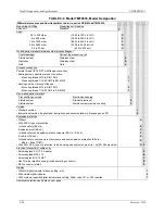
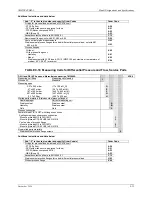
Additional selections and data below
Add “–Z” to the order number and specify Order Codes
Order Code
O-rings for process flanges (instead of FPM (Viton)):
- PTFE (Teflon)
A20
- FEP (with silicone core, approved for food)
A21
- FFPM (Kalrez, compound 4079)
A22
- NBR (Buna N)
A23
Acceptance test certificate to EN 10204-3.1
C12
Process connection G1/2A
D16
Remote seal flanges; not with K01, K02 or K04
D20
Vent on side for gas measurement
H02
Process flanges
Without
K00
With process flange made of:
- Hastelloy
K01
- Monel
K02
- Stainless steel with PVDF insert; PN 10 (MWP 145 psi) maximum, temperature of
medium 90°C (194°F) maximum
K04
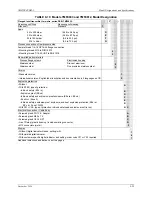
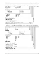
TABLE 9-15 Measuring Cells for Pressure and Flow, Differential Const., Service Parts
DS III and DS III PA series, differential construction, 7MF4994-
- 0DC0
Measuring cell filling
Measuring cell cleaning
Silicon oil
Normal
1
Inert liquid
Grease-free
3
Measuring span
PN 32 (MWP 464 psi)
1 to 20 mbar (0.4 to 8 in H
2
O)
B
PN 160 (MWP 2320 psi)
1 to 60 mbar (0.4 to 24 in H
2
O)
C
2.5 to 250 mbar (1 to 100 inH
2
O)
D
6 to 600 mbar (2.4 to 240 in H
2
O)
E
16 to 1600 mbar (6.42 to 640 inH
2
O)
F
50 to 5000 mbar (20 to 2000 inH
2
O)
G
0.3 to 30 bar (4.35 to 435 psi)
H
Wetted parts materials (stainless steel process flanges)
Seal diaphragm
Parts of measuring cell
Stainless steel
Stainless steel
A
Hastelloy
Stainless steel
B
Hastelloy
Hastelloy
C
Tantalum
Tantalum
E
Monel
Monel
H
Gold
Gold
L
Process connection
Female thread 1/4-18 NPT with flange connection
Sealing screw opposite process connection
- Mounting thread M10 to DIN 19213
0
- Mounting thread 7/16-20 UNF To EN 61518
2
Vent on side of process flange
- Mounting thread M10 to DIN 19213
4
- Mounting thread 7/16-20 UNF to EN 61518
6
Non-wetted parts materials
Stainless steel process flange screws
2
See the next page for additional selections and data.
Содержание 7MF4033 series
Страница 48: ...Model 275 Universal Hart Communicator UMSITRPDS3 1 November 2010 2 26 ...
Страница 86: ...Installation UMSITRPDS3 1 November 2010 4 34 ...
Страница 152: ...Calibration and Maintenance UMSITRPSD3 1 November 2010 7 20 ...
Страница 158: ...Circuit Description UMSITRPDS3 1 November 2010 8 6 ...
Страница 197: ......
Страница 198: ......
Страница 200: ...Model Designations and Specifications UMSITRPDS3 1 November 2010 9 42 ...
Страница 204: ...Glossary UMSITRPDS3 1 November 2010 10 4 ...
Страница 208: ...Appendix A Online Configuration Map UMSITRPDS3 1 11 4 November 2010 ...
Страница 210: ...Appendix B Hazardous Area Installation UMSITRPDS3 1 12 2 November 2010 FIGURE 12 1 Control Drawing ...
Страница 211: ...UMSITRPDS3 1 Appendix B Hazardous Area Installation November 2010 12 3 FIGURE 12 2 Control Drawing ...
Страница 212: ...Appendix B Hazardous Area Installation UMSITRPDS3 1 12 4 November 2010 FIGURE 12 3 Control Drawing ...
Страница 216: ...Appendix C Elevation and Suppression Correction UMSITRPDS3 1 13 4 November 2010 ...


