Circuit Description
UMSITRPDS3-1
November
2010
8-2
8.1 OVERALL OPERATION
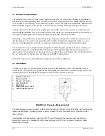
The measuring cell sensor (1) detects the applied process pressure. The sensor’s analog output signal is
amplified by an instrument amplifier (2) and converted into a digital signal in an analog-digital converter
(3). This data is evaluated by a microcontroller (4) that corrects the signal and temperature characteristics.
Microcontroller output is converted to a 4-20 mA output current by the digital-analog converter (5).
A diode circuit (10) provides reverse polarity protection in the event of reversed loop connections. An
external digital milliammeter can be connected across the diode. The diode and the electronics discussed
in the previous paragraph are housed in an assembly named the electronics module.
Measuring cell-specific data (e.g. measuring range, measuring cell material, oil fill) are stored in a non-
volatile memory (6) located in the measuring cell assembly. Transmitter configuration data (e.g. turn-
down, electric damping) are stored in a second non-volatile memory (6) in the electronics module.
The transmitter can be configured locally using three built-in magnetic pushbuttons (8) or remotely, via
the HART modem (7), using the HART Communicator. The digital display (9) shows input pressure,
output current, error messages, modes of operation, or other data as determined by the configuration and
by user commands via the magnetic pushbuttons or HART Communicator.
In the following sections, individual measuring cell types will be explained.
8.2 PRESSURE
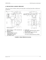
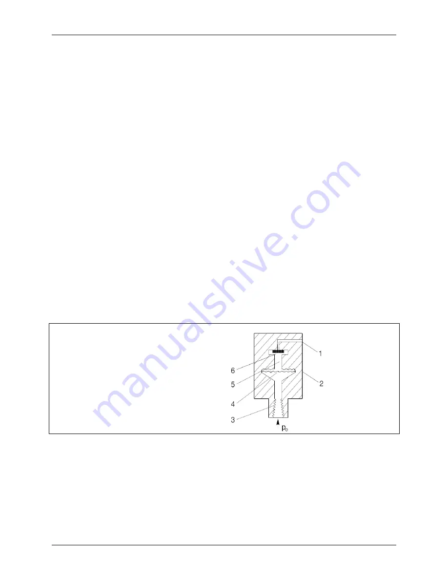
As shown in Figure 8-2, process pressure p
e
is applied to the measuring cell (2) through the process
connection (3). This pressure is applied to the seal diaphragm which flexes to transfer the pressure to the
fill fluid (5) which in turn transfers the pressure to the silicon pressure sensor (6).
1
2
3
4
5
6
p
e
Reference pressure
Measuring cell
Process connection
Seal diaphragm
Filling fluid
Silicon pressure sensor
Input variable pressure
FIGURE 8-2 Pressure Measuring Cell
The silicon pressure sensor consists of four piezo-resistors in a bridge circuit. The bridge is located on the
measuring diaphragm. Applied pressure causes a change in bridge resistance that is proportion to the
input pressure.
A transmitter with a measuring span of up to 925 psi will measure the input pressure compared to
atmospheric pressure. A transmitter with a measuring span of 2320 psi (or greater) compares input
pressure to a vacuum.
Содержание 7MF4033 series
Страница 48: ...Model 275 Universal Hart Communicator UMSITRPDS3 1 November 2010 2 26 ...
Страница 86: ...Installation UMSITRPDS3 1 November 2010 4 34 ...
Страница 152: ...Calibration and Maintenance UMSITRPSD3 1 November 2010 7 20 ...
Страница 158: ...Circuit Description UMSITRPDS3 1 November 2010 8 6 ...
Страница 197: ......
Страница 198: ......
Страница 200: ...Model Designations and Specifications UMSITRPDS3 1 November 2010 9 42 ...
Страница 204: ...Glossary UMSITRPDS3 1 November 2010 10 4 ...
Страница 208: ...Appendix A Online Configuration Map UMSITRPDS3 1 11 4 November 2010 ...
Страница 210: ...Appendix B Hazardous Area Installation UMSITRPDS3 1 12 2 November 2010 FIGURE 12 1 Control Drawing ...
Страница 211: ...UMSITRPDS3 1 Appendix B Hazardous Area Installation November 2010 12 3 FIGURE 12 2 Control Drawing ...
Страница 212: ...Appendix B Hazardous Area Installation UMSITRPDS3 1 12 4 November 2010 FIGURE 12 3 Control Drawing ...
Страница 216: ...Appendix C Elevation and Suppression Correction UMSITRPDS3 1 13 4 November 2010 ...

