UMSITRPDS3-1
Appendix A - Online Configuration Map
November 2010
11-1
11.0 APPENDIX A - ONLINE CONFIGURATION MAP
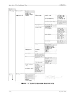
This Appendix contains a detailed configuration map showing the available online configuration options
when using the Model 275 HART Communicator – see the Note below.
To use the map:
1.
Connect the Model 275 HART Communicator to a powered SITRANS P DSIII transmitter. See
Section 2 Model 275 HART Communicator and Section 4 Installation.
2.
Press the Communicator's I/O key to turn it on. A Communicator self-test routine will be initiated
and, upon successful completion, the Communicator will poll the connected transmitter(s).
3.
When the Online menu appears, press 3 to access the Device Setup menu, if configuring or servicing
the transmitter.
Note that 5 items appear in the Device Setup menu. The first three: 1 Process Variables, 2
Diagnostics/Service, and 3 Basic Setup are mapped in Figure A-1 Part 1. The last two: 4 Detailed
Setup and 5 Review are mapped in Figure A-1 Part 2. The figures are on facing pages for ease of use.
Note: The Configuration Map for the Model 375 Field
Communicator is shown at the back of this manual. Be
sure to read the manual supplied with the Model 375
before installing or using the device.
Содержание 7MF4033 series
Страница 48: ...Model 275 Universal Hart Communicator UMSITRPDS3 1 November 2010 2 26 ...
Страница 86: ...Installation UMSITRPDS3 1 November 2010 4 34 ...
Страница 152: ...Calibration and Maintenance UMSITRPSD3 1 November 2010 7 20 ...
Страница 158: ...Circuit Description UMSITRPDS3 1 November 2010 8 6 ...
Страница 197: ......
Страница 198: ......
Страница 200: ...Model Designations and Specifications UMSITRPDS3 1 November 2010 9 42 ...
Страница 204: ...Glossary UMSITRPDS3 1 November 2010 10 4 ...
Страница 208: ...Appendix A Online Configuration Map UMSITRPDS3 1 11 4 November 2010 ...
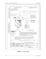
Страница 210: ...Appendix B Hazardous Area Installation UMSITRPDS3 1 12 2 November 2010 FIGURE 12 1 Control Drawing ...
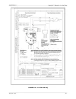
Страница 211: ...UMSITRPDS3 1 Appendix B Hazardous Area Installation November 2010 12 3 FIGURE 12 2 Control Drawing ...
Страница 212: ...Appendix B Hazardous Area Installation UMSITRPDS3 1 12 4 November 2010 FIGURE 12 3 Control Drawing ...
Страница 216: ...Appendix C Elevation and Suppression Correction UMSITRPDS3 1 13 4 November 2010 ...

