UMSITRPDS3-1
Installation
November 2010
4-33
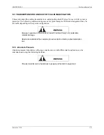
4.7 HAZARDOUS AREA INSTALLATION
Drawings providing transmitter installation data for hazardous areas are located in Appendix B Hazardous
Area Installation. Entity parameters, barrier selection, and important wiring information are specified on
these drawings. The appendix also contains a list of tested barriers.
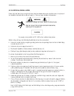
WARNING
Explosion can cause death or serious injury.
In a Division 1 area, where an explosion-proof rating is
required, remove power from the transmitter before removing
either enclosure cap. When replacing an enclosure cap, it
must be screwed onto the enclosure until the O-ring is
sufficiently compressed to prevent leakage into the
enclosure. Cap locks may be required.
All pertinent regulations regarding installation in a hazardous
area must be observed.
Before installing a transmitter in a hazardous area, check the rating and approval plates on the transmitter
and Section 9 Model Designation and Specifications for required approvals or certifications.
Explosion-Proof Installation
If the installation is required to be explosion-proof as defined by the National Electrical Code, refer to a
current copy of the Code and the following:
•
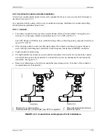
User-supplied explosion-proof conduit seals (glands) are required on transmitter housing conduit
outlets and any installed junction boxes. See Figure 4-16.
•
Explosion-proof glands must provide a good seal. Apply a sealing compound around the sealing
surface if necessary.
•
Power wiring conduit entries at the transmitter must have a minimum of five threads fully engaged.
•
The enclosure cap must be installed and have a minimum of eight threads fully engaged with no
damaged threads permitted.
•
Go to Section 4.6 for wiring connections to the transmitter’s terminals. Refer to Appendix B for
hazardous area installation.
This completes the physical installation.
!
Содержание 7MF4033 series
Страница 48: ...Model 275 Universal Hart Communicator UMSITRPDS3 1 November 2010 2 26 ...
Страница 86: ...Installation UMSITRPDS3 1 November 2010 4 34 ...
Страница 152: ...Calibration and Maintenance UMSITRPSD3 1 November 2010 7 20 ...
Страница 158: ...Circuit Description UMSITRPDS3 1 November 2010 8 6 ...
Страница 197: ......
Страница 198: ......
Страница 200: ...Model Designations and Specifications UMSITRPDS3 1 November 2010 9 42 ...
Страница 204: ...Glossary UMSITRPDS3 1 November 2010 10 4 ...
Страница 208: ...Appendix A Online Configuration Map UMSITRPDS3 1 11 4 November 2010 ...
Страница 210: ...Appendix B Hazardous Area Installation UMSITRPDS3 1 12 2 November 2010 FIGURE 12 1 Control Drawing ...
Страница 211: ...UMSITRPDS3 1 Appendix B Hazardous Area Installation November 2010 12 3 FIGURE 12 2 Control Drawing ...
Страница 212: ...Appendix B Hazardous Area Installation UMSITRPDS3 1 12 4 November 2010 FIGURE 12 3 Control Drawing ...
Страница 216: ...Appendix C Elevation and Suppression Correction UMSITRPDS3 1 13 4 November 2010 ...


