UMSITRPDS3-1
On-Line Operation
November 2010
6-11
After adjusting, the measuring span specified on the rating plate may no longer match the new span.
A turn-down up to a maximum 100:1 (span ratio = r, turn-down) can be reached depending on the series
and the measuring range.
The relationship between the measured pressure and the generated output current is linear, except for the
square root characteristic in differential pressure transmitters.
Example:
1.
Given: a transmitter with a measuring span of 0 to 232 psi. Adjust it to a measuring span of 29 to 203
psi without applying a reference pressure. (The assumed pressure will be zero psi or the lower sensor
limit whichever is greater.)
2.
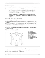
Press the M pushbutton to select mode 5.
3.
Adjust zero to 29 psi by pressing the
(
or
'
pushbutton.
4.
Press the M pushbutton to save the value and select mode 6.
5.
Adjust full scale to 203 psi by pressing the
(
or
'
pushbutton.
6.
Press the M pushbutton to save the value.
6.2.4.2 Practical Applications
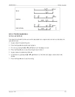
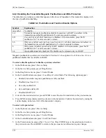
Set zero and full scale (blind):
1.
Select the pressure input engineering unit.
2.
Press the M pushbutton to select mode 5.
3.
Press the
(
and
'
pushbuttons simultaneously and hold for 2 seconds. Zero is set to lower sensor
limit.
4.
Press the M pushbutton to save the value and select mode 6.
5.
Press the
(
or
'
pushbuttons and hold for 2 seconds. Full scale is set to the upper sensor limit.
6.
Press the M pushbutton to save the value.
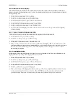
Adjust zero and full scale (blind):
1.
Select the pressure input engineering unit.
2.
Press the M pushbutton to select mode 5.
3.
Adjust zero by pressing the
(
or
'
pushbutton. This value will produce 4 mA.
4.
Press the M pushbutton to save the input pressure value and select mode 6.
5.
Adjust full scale by pressing the
(
or
'
pushbutton. This value will produce 20 mA.
6.
Press the M pushbutton to save the input pressure value.
Содержание 7MF4033 series
Страница 48: ...Model 275 Universal Hart Communicator UMSITRPDS3 1 November 2010 2 26 ...
Страница 86: ...Installation UMSITRPDS3 1 November 2010 4 34 ...
Страница 152: ...Calibration and Maintenance UMSITRPSD3 1 November 2010 7 20 ...
Страница 158: ...Circuit Description UMSITRPDS3 1 November 2010 8 6 ...
Страница 197: ......
Страница 198: ......
Страница 200: ...Model Designations and Specifications UMSITRPDS3 1 November 2010 9 42 ...
Страница 204: ...Glossary UMSITRPDS3 1 November 2010 10 4 ...
Страница 208: ...Appendix A Online Configuration Map UMSITRPDS3 1 11 4 November 2010 ...
Страница 210: ...Appendix B Hazardous Area Installation UMSITRPDS3 1 12 2 November 2010 FIGURE 12 1 Control Drawing ...
Страница 211: ...UMSITRPDS3 1 Appendix B Hazardous Area Installation November 2010 12 3 FIGURE 12 2 Control Drawing ...
Страница 212: ...Appendix B Hazardous Area Installation UMSITRPDS3 1 12 4 November 2010 FIGURE 12 3 Control Drawing ...
Страница 216: ...Appendix C Elevation and Suppression Correction UMSITRPDS3 1 13 4 November 2010 ...


