Post-Installation Test
UMSITRPDS3-1
November
2010
5-10
8.
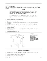
Close the active pressure valve (2).
9.
Open the active pressure valve (3B) slightly until air-free liquid emerges, then close it.
10.
Close the vent valve at the low-pressure chamber (1).
11.
Open the active pressure valve (3A) by 1/2 turn.
12.
Check and correct zero (4 mA) if necessary at zero bar.
13.
Close the compensation valve (2).
14.
Open the active pressure valves (3A and 3B) fully.
Transmitter
above
the active pressure taps (normal
arrangement)
Transmitter
below
the active pressure taps
(exception)
1
2
3
4
Transmitter
Compensation valve
Active pressure valves
Active pressure lines
5
7
10
12
Shutoff valves
Blowout valves
Active pressure taps
Gas collectors (optional)
FIGURE 5-5 Measuring Liquids
Содержание 7MF4033 series
Страница 48: ...Model 275 Universal Hart Communicator UMSITRPDS3 1 November 2010 2 26 ...
Страница 86: ...Installation UMSITRPDS3 1 November 2010 4 34 ...
Страница 152: ...Calibration and Maintenance UMSITRPSD3 1 November 2010 7 20 ...
Страница 158: ...Circuit Description UMSITRPDS3 1 November 2010 8 6 ...
Страница 197: ......
Страница 198: ......
Страница 200: ...Model Designations and Specifications UMSITRPDS3 1 November 2010 9 42 ...
Страница 204: ...Glossary UMSITRPDS3 1 November 2010 10 4 ...
Страница 208: ...Appendix A Online Configuration Map UMSITRPDS3 1 11 4 November 2010 ...
Страница 210: ...Appendix B Hazardous Area Installation UMSITRPDS3 1 12 2 November 2010 FIGURE 12 1 Control Drawing ...
Страница 211: ...UMSITRPDS3 1 Appendix B Hazardous Area Installation November 2010 12 3 FIGURE 12 2 Control Drawing ...
Страница 212: ...Appendix B Hazardous Area Installation UMSITRPDS3 1 12 4 November 2010 FIGURE 12 3 Control Drawing ...
Страница 216: ...Appendix C Elevation and Suppression Correction UMSITRPDS3 1 13 4 November 2010 ...


