Model 275 Universal Hart Communicator
UMSITRPDS3-1
November
2010
2-2
MG
00360a
HART Communicator
I
O
F1
F2
F3
F4
1
3
4
5
6
7
8
9
0
# % &
S T U
J K L
A B C
D E F
G H I
M N O
P Q R
V W X
Y Z /
< >
.
*
_
2
:
+
1
2
3
4
5
6
7
8
9
10
11
12
1
2
3
4
5
6
7
8
9
10
11
12
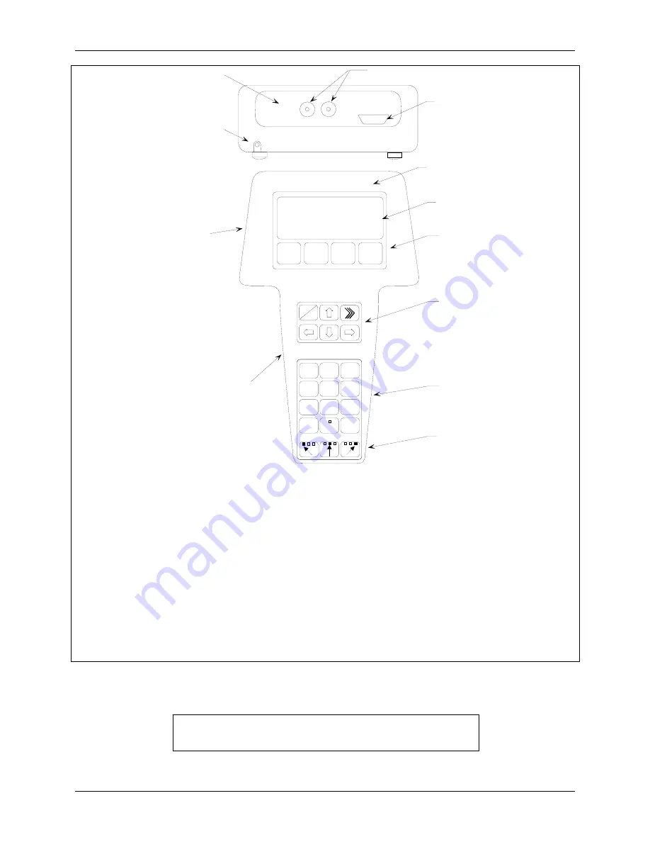
Model 275 Universal HART Communicator
Liquid Crystal Display (LCD), 8 lines, 21 characters per line
Function Keys (softkeys), software defined
Action Keys – ON/OFF (I/O), Up Arrow, Quick Access Key (>>>), Previous Menu (Back, left arrow),
Down Arrow, Select (Forward, right arrow)
Alphanumeric Keys (keypad number sequence may be different from that shown)
Shift Keys – Use to select alphabetic and other characters above a number, period, or dash.
Communicator Nameplate – On back of device. See nameplate for certifications and approvals
before connecting in a hazardous location.
Communicator model number and serial number on back
Connection panel.
Non-polar loop connection; dual banana plug
Serial port for PC connection; DB9
NiCad Charger Jack, optional
FIGURE 2-1 Model 275 Universal HART Communicator
Note: If using a Model 375 Field Communicator, see the
inside of the front cover of this manual.
Содержание 7MF4033 series
Страница 48: ...Model 275 Universal Hart Communicator UMSITRPDS3 1 November 2010 2 26 ...
Страница 86: ...Installation UMSITRPDS3 1 November 2010 4 34 ...
Страница 152: ...Calibration and Maintenance UMSITRPSD3 1 November 2010 7 20 ...
Страница 158: ...Circuit Description UMSITRPDS3 1 November 2010 8 6 ...
Страница 197: ......
Страница 198: ......
Страница 200: ...Model Designations and Specifications UMSITRPDS3 1 November 2010 9 42 ...
Страница 204: ...Glossary UMSITRPDS3 1 November 2010 10 4 ...
Страница 208: ...Appendix A Online Configuration Map UMSITRPDS3 1 11 4 November 2010 ...
Страница 210: ...Appendix B Hazardous Area Installation UMSITRPDS3 1 12 2 November 2010 FIGURE 12 1 Control Drawing ...
Страница 211: ...UMSITRPDS3 1 Appendix B Hazardous Area Installation November 2010 12 3 FIGURE 12 2 Control Drawing ...
Страница 212: ...Appendix B Hazardous Area Installation UMSITRPDS3 1 12 4 November 2010 FIGURE 12 3 Control Drawing ...
Страница 216: ...Appendix C Elevation and Suppression Correction UMSITRPDS3 1 13 4 November 2010 ...

