UMSITRPDS3-1
Pre-Installation Test
November 2010
3-1
3.0 PRE-INSTALLATION TEST
Prior to installation, the transmitter can be tested and operated from the HART Communicator. This test
consists of checking that the transmitter is operational and that all configuration information is correct.
Section 5 Post-Installation Test provides an on-line test procedure. For an in-depth discussion of
transmitter configuration, refer to Section 6 On-Line Configuration and Operation.
IMPORTANT
Transmitter orientation will affect the analog output zero. Refer to Section 7.1
Calibration for details.
3.1 PROCEDURE
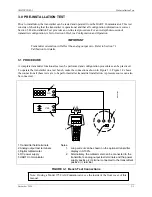
A complete transmitter functional test can be performed and configuration procedures can be practiced.
To operate the transmitter on a test bench, make the connections shown in Figure 3-1. Figure 3-2 shows
the connections if these tests are to be performed after transmitter installation. A pressure source can also
be connected.
+
_
- +
4-20 mA
+
_
I
O
M
G
00
357
a
_
+
250
mA
Vdc
1
2
3
4
5
1 Transmitter field terminals
2 Analog output test terminals
3 Digital milliammeter
4 DC power supply
5 HART Communicator
Notes:
1.
2.
Loop current can be shown on the optional transmitter
display in 0-100%.
Alternatively, the milliammeter can be connected to the
transmitter’s analog output test terminals and the power
supply positive (+) terminal connected to the transmitter’s
positive (+) terminal.
FIGURE 3-1 Bench Test Connections
Note: If using a Model 375 Field Communicator, see the inside of the front cover of this
manual.
Содержание 7MF4033 series
Страница 48: ...Model 275 Universal Hart Communicator UMSITRPDS3 1 November 2010 2 26 ...
Страница 86: ...Installation UMSITRPDS3 1 November 2010 4 34 ...
Страница 152: ...Calibration and Maintenance UMSITRPSD3 1 November 2010 7 20 ...
Страница 158: ...Circuit Description UMSITRPDS3 1 November 2010 8 6 ...
Страница 197: ......
Страница 198: ......
Страница 200: ...Model Designations and Specifications UMSITRPDS3 1 November 2010 9 42 ...
Страница 204: ...Glossary UMSITRPDS3 1 November 2010 10 4 ...
Страница 208: ...Appendix A Online Configuration Map UMSITRPDS3 1 11 4 November 2010 ...
Страница 210: ...Appendix B Hazardous Area Installation UMSITRPDS3 1 12 2 November 2010 FIGURE 12 1 Control Drawing ...
Страница 211: ...UMSITRPDS3 1 Appendix B Hazardous Area Installation November 2010 12 3 FIGURE 12 2 Control Drawing ...
Страница 212: ...Appendix B Hazardous Area Installation UMSITRPDS3 1 12 4 November 2010 FIGURE 12 3 Control Drawing ...
Страница 216: ...Appendix C Elevation and Suppression Correction UMSITRPDS3 1 13 4 November 2010 ...

