User Manual Of EL7-EC** AC Servo
71
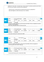
Pr1.01
Label
1
st
velocity loop gain
Mode
F
Range
1~32767 Unit
0.1Hz Default
180
Index
2101h
Activation
Immediate
To determine the responsiveness of the velocity loop. If inertia ratio of Pr0.04 is uniform with
actual inertia ratio, velocity loop responsiveness = Pr1.01.
To increase position loop gain and improve responsiveness of the whole system, velocity loop
gain must be set at higher value. Please notice that if the velocity loop gain is too high, it might
cause vibration.
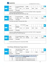
Pr1.02
Label
1
st
Integral Time Constant
of Velocity Loop
Mode
F
Range
1~10000 Unit
0.1ms Default
310
Index
2102h
Activation
Immediate
If auto gain adjusting function is not enabled, Pr1.02 is activated.
The lower the set value, the closer the lag error at stop to 0 but might cause vibration. If the
value set is overly large, overshoot, delay of positioning time duration and lowered
responsiveness might occur.
Set 10000 to deactivate Pr1.02.
Recommended range: 50000
≤
PA1.01xPA1.02
≤
150000
For example: Velocity loop gain Pr1.01=500(0.1Hz), which is 50Hz. Integral time constant of
velocity loop should be 100(0.1ms)
≤
Pr1.02
≤
300(0.1ms)
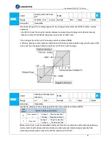
Pr1.03
Label
1
st
velocity detection filter Mode
F
Range
0~10000 Unit
—
Default
15
Index
2103h
Activation
Immediate
This filter is a low pass filter. It blocks high frequencies which cause system instability from
velocity feedback data. The higher the set value, lower frequencies will be blocked and velocity
responsiveness will also be lowered. Pr1.03 needs to match velocity loop gain. Please refer to
the following table.
Set
Value
Velocity Detection
Filter Cut-off
Frequency(Hz)
Set
Value
Velocity Detection Filter
Cut-off Frequency(Hz)
0
2500
16
750
1
2250
17
700
2
2100
18
650
3
2000
19
600
4
1800
20
550
5
1600
21
500
6
1500
22
450
7
1400
23
400
8
1300
24
350
9
1200
25
300
10
1100
26
250
11
1000
27
200
12
950
28
175
13
900
29
150
14
850
30
125
15
800
31
100


