User Manual Of EL7-EC** AC Servo
144
25
d25PF
Motor electrical angle
d25PF
pulse
“ xxxx”
26
d26hy
Motor mechanical angle
d26hy
pulse
“ xxxx”
27
d27 Pn
Voltage across PN
d27Pn
V
“ xxxx”
28
d28 no
Software version
d28no
/
“d xxx Servo software”
“F xxx Communication
software”
“p xxx Servo power
rating”
29
d29AS
Internal usage
d29AS
/
“xxx”
30
d30NS
No. of times of encoder
communication error
d30sE
/
“xxx”
31
d31 tE
Accumulated operation
time
d31tE
/
“ xxxx”
32
d32Au
Automatic motor
identification
d32Au
/
“r xxx Motor no.”
“E xxx Servo no.”
33
d33At
Driver temperature
d33At
℃
“xxx”
34
d34
Servo status
d34
/
“xxx”
35
d35 SF
Internal usage
d35SF
/
“xxxxxx”
Following are parameters related to EtherCAT bus
36
d36
Synchronizing cycle
d36dc
ms
“xxxxxx”
37
d37
No. of times of
synchronization loss
d37sc
/
“xxxxxx”
38
d38
Synchronization Type
d38st
freeru
n/DC
“xxxxxx”
39
d39
If DC is running
d39dr
/
“xxxxxx”
40
d40
Acceleration and
deceleration status
d40sn
/
“xxxxxx”
41
d41
Object dictionary address
d41od
/
“xxxxxx”
Index(4 bit)+subindex(2
bit)
42
d42
Object dictionary value
d42od
/
“xxxxxx”
1
、
If OD does not exist,
ODNEXT is displayed.
2
、
If OD is out of range,
ODRNG is displayed.
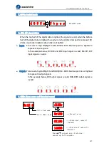
If EtherCAT is not connected, "
" is displayed after power on.
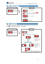
Description of data monitoring function
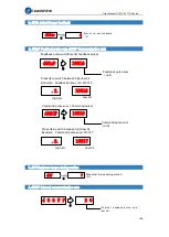
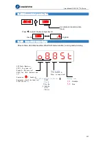
When using the front panel to monitor data, data is divided in low/high bit and
positive/negative.
Data is differentiated as below.
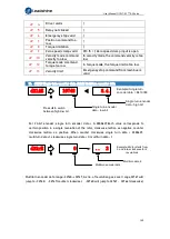
. 2 .
6 0 8 8 5
High bit
:
1
st
and
2
nd
values
on the right
has two decimal points
Low bit
:
1
st
and
2
nd
values
on the right
has no
decimal point
.


