User Manual Of EL7-EC** AC Servo
15
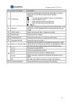
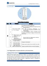
No. Parts & Connectors
Description
○
1 Front Panel
Including a LED display and 5 buttons. LED display is used to
display servo drive status and parameter settings.
5 buttons
:
M
:
To switch between different modes and parameters
◀
:
Switch between value
▲
:
Switch between sub-menus/Increase
▼
:
Switch between sub-menus/Decrease
S :
Enter
○
2 USB mini
Connect to computer for tuning of servo drive. Parameters of the
servo drive can be modified without connecting to main power
supply.
○
3 CN1 I/O signal
Probe input signal & other I/O signals terminals
○
4
CN2 Encoder
Connect to motor encoder
○
5 CN3 EtherCAT IN
Connect to master device or previous slave station
○
6 CN4 EtherCAT OUT
Connect to next slave station
○
7 Power-on indicator light
Lights up when servo drive is connected to main power supply.
Please do not touch the power terminal immediately after power
off as the capacitor might require some time to discharge.
○
8
L1, L2
Main power supply 220VAC
P+, Br
Connect to regenerative resistor
P+, N
Common DC bus terminals for multiple drivers
U, V, W
Motor connector: Connect to U,V,W power terminals on servo
motor
PE
PE motor earth terminal: Connect to motor PE terminal
○
9 Protective Earth PE
Connect to PE of main power supply. For grounding

