User Manual Of EL7-EC** AC Servo
42
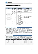
2.10 CN1 I/O Signal Port
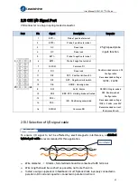
CN1 connector is a 16-pin spring loaded connector.
Port
Pin
Signal
Description
Remarks
1
EXT1
+
Probe 1 positive terminal
2 high speed probe
inputs function
2
EXT2
+
Probe 2 positive terminal
3
NC
Reserved
4
NC
Reserved
5
EXT1 -
Probe 1 negative terminal
6
EXT2 -
Probe 2 negative terminal
7
DICOM
Common DI
Double-ended common DI
Configurable
Recommended voltage:
12VDC - 24VDC
9
DI1
Reserved
11
DI2
POT
:
Positive limit switch
13
DI3
NOT
:
Negative limit switch
15
DI4
HOME
:
Homing done
8
DO1
ALM
:
Alarm
D01,D02: Single-ended
D03: Double-ended
Configurable
Recommended voltage:
12Vdc – 24Vdc, max 30V
Recommended current:
10mA, max 50mA
10
DO2
BRK-OFF
:
Holding brake activated
12
DO3
+
INP
:
Positioning completed
14
DO3
-
16
DOCOM
Common DO
2.10.1 Selection of I/O signal cable
I/O signal cable
To ensure I/O signal to not be affected by electromagnetic interference, a shielded
twisted pair cable is recommended for this application.
Wire diameter
≥
0.14mm
2
, foil shielded should be connected to PE terminal.
Wire length should be as short as possible, not more than 3m.
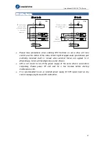
Install a surge suppressor in feedback circuit; flyback diode inversely connected in
parallel in DC coil and capacitor connected in parallel in AC coil.
Foil shield


