ii
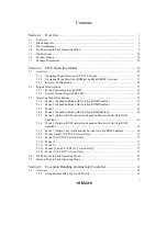
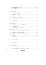
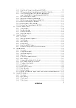
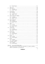
3.2 Interrupt
Controller ............................................................................................................
54
3.2.1
Interrupt Controller Features ................................................................................
54
3.2.2 Block
Diagram......................................................................................................
55
3.2.3 Pin
Configuration .................................................................................................
56
3.2.4 Register
Configuration .........................................................................................
57
3.3 Register
Descriptions.........................................................................................................
58
3.3.1
Interrupt Control Register (INTCR) .....................................................................
58
3.3.2
Interrupt Priority Registers A to K (IPRA to IPRK) ............................................
59
3.3.3
IRQ Enable Register (IER)...................................................................................
60
3.3.4
IRQ Sense Control Registers H and L (ISCRH, ISCRL) .....................................
61
3.3.5
IRQ Status Register (ISR) ....................................................................................
62
3.3.6
IRQ Pin Select Register (ITSR) ...........................................................................
64
3.3.7
Software Standby Release IRQ Enable Register (SSIER) ...................................
65
3.4 Interrupt
Sources................................................................................................................
66
3.4.1 External
Interrupts ................................................................................................
66
3.4.2 Internal
Interrupts .................................................................................................
67
3.4.3
Interrupt Vector Table ..........................................................................................
68
3.5 Interrupt
Operation.............................................................................................................
74
3.5.1
Interrupt Control Modes and Interrupt Operation ................................................
74
3.5.2
Interrupt Control Mode 0......................................................................................
77
3.5.3
Interrupt Control Mode 2......................................................................................
79
3.5.4
Interrupt Exception Handling Sequence...............................................................
81
3.5.5
Interrupt Response Times.....................................................................................
83
3.6 Usage
Notes .......................................................................................................................
84
3.6.1
Contention between Interrupt Generation and Disabling .....................................
84
3.6.2
Instructions that Disable Interrupts.......................................................................
85
3.6.3
Periods when Interrupts are Disabled...................................................................
85
3.6.4
Interrupts during Execution of EEPMOV Instruction ..........................................
85
3.7
DTC and DMAC Activation by Interrupt..........................................................................
85
3.7.1 Overview...............................................................................................................
85
3.7.2 Block
Diagram......................................................................................................
86
3.7.3 Operation ..............................................................................................................
87
Section 4
Bus Controller
..................................................................................................
91
4.1 Overview............................................................................................................................
91
4.1.1 Features.................................................................................................................
91
4.1.2 Block
Diagram .....................................................................................................
93
4.1.3 Pin
Configuration .................................................................................................
94
4.1.4 Register
Configuration .........................................................................................
96
4.2 Register
Descriptions.........................................................................................................
97
4.2.1
Bus Width Control Register (ABWCR) ...............................................................
97
4.2.2
Access State Control Register (ASTCR)..............................................................
97
4.2.3
Wait Control Registers A and B (WTCRA, WTCRB).........................................
98
Содержание H8S/2670
Страница 5: ......
Страница 9: ......
Страница 199: ...182 ...
Страница 361: ...344 ...
Страница 393: ...376 ...
Страница 647: ...630 ...

