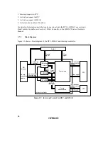
77
3.5.2
Interrupt Control Mode 0
Enabling and disabling of IRQ interrupts and on-chip supporting module interrupts can be set by
means of the I bit in the CPU’s CCR. Interrupts are enabled when the I bit is cleared to 0, and
disabled when the I bit is set to 1.
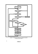
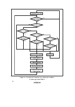
Figure 3.5 shows a flowchart of the interrupt acceptance operation in this case.
1. If an interrupt source occurs when the corresponding interrupt enable bit is set to 1, an interrupt
request is sent to the interrupt controller.
2. The I bit is then referenced. If the I bit is cleared to 0, the interrupt request is accepted. If the I
bit is set to 1, only an NMI interrupt is accepted, and other interrupt requests are held pending.
3. Interrupt requests are sent to the interrupt controller, the highest-priority interrupt according to
the priority order is selected, and the others are held pending.
4. When an interrupt request is accepted, processing for the instruction being executed at that
time is completed before interrupt exception handling is started.
5. PC and CCR are saved to the stack area in interrupt exception handling. The PC value saved
on the stack shows the address of the first instruction to be executed after returning from the
interrupt service routine.
6. Next, the I bit in CCR is set to 1. This masks all interrupts except NMI.
7. A vector address is generated for the accepted interrupt, and execution of the interrupt service
routine starts at the address indicated by the contents of that vector address.
Содержание H8S/2670
Страница 5: ......
Страница 9: ......
Страница 199: ...182 ...
Страница 361: ...344 ...
Страница 393: ...376 ...
Страница 647: ...630 ...


