75
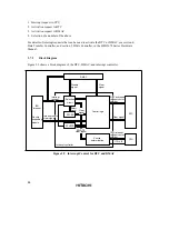
Figure 3.4 shows a block diagram of the priority decision circuit.
8-level
mask control
Interrupt source
Interrupt
control
mode 0
I
Interrupt
acceptance
control
Default priority
determination
Vector number
I2 to I0
IPR
Interrupt control mode 2
Figure 3.4 Block Diagram of Interrupt Control Operation
Interrupt Acceptance Control: In interrupt control mode 0, interrupt acceptance control is
performed by means of the I bit in CCR.
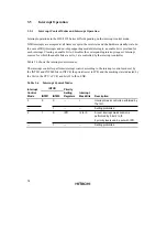
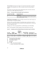
Table 3.7 shows the interrupts that can be selected in each interrupt control mode.
Table 3.7
Interrupts Selected in Each Interrupt Control Mode (1)
Interrupt Mask Bit
Interrupt Control Mode
I
Selected Interrupts
0
0
All interrupts
1
NMI interrupt
2
*
All interrupts
*
: Don’t care
Содержание H8S/2670
Страница 5: ......
Страница 9: ......
Страница 199: ...182 ...
Страница 361: ...344 ...
Страница 393: ...376 ...
Страница 647: ...630 ...


