171
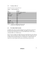
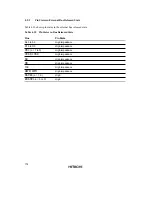
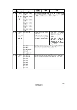
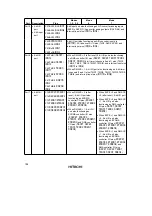
Table 4.8 shows when idle cycles are inserted in the case of mixed accesses to normal space and
DRAM space.
Table 4.8
Idle Cycles in Mixed Accesses to Normal Space and DRAM Space
Previous Access
Next Access
ICIS1
ICIS0
DRMI
IDLC
Idle cycle
Normal space read
Normal space read
1
—
—
0
1 state inserted
(different area)
1
2 states inserted
Normal space read
DRAM space read
1
—
—
0
1 state inserted
1
2 states inserted
Normal space read
Normal space write
—
1
—
0
1 state inserted
1
2 states inserted
Normal space read
DRAM space write
—
1
—
0
1 state inserted
1
2 states inserted
DRAM space read
Normal space read
1
—
0
—
Disabled
1
0
1 state inserted
1
2 states inserted
DRAM space read
DRAM space read
1
—
0
—
Disabled
1
0
1 state inserted
1
2 states inserted
DRAM space read
Normal space write
—
1
0
—
Disabled
1
0
1 state inserted
1
2 states inserted
DRAM space read
DRAM space write
—
1
0
—
Disabled
1
0
1 state inserted
1
2 states inserted
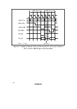
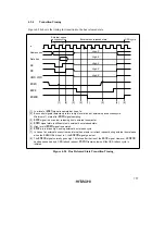
Setting the DRMI bit to 1 enables an idle cycle to be inserted in the case of consecutive read and
write operations in DRAM space burst access. Figure 4.52 shows an example of the timing for idle
cycle insertion in the case of consecutive read and write accesses to DRAM space.
Содержание H8S/2670
Страница 5: ......
Страница 9: ......
Страница 199: ...182 ...
Страница 361: ...344 ...
Страница 393: ...376 ...
Страница 647: ...630 ...


