423
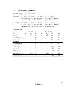
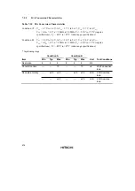
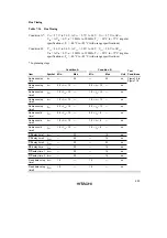
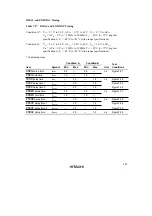
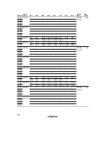
Bus Timing
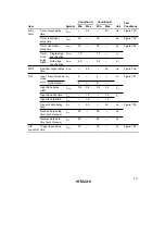
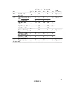
Table 7.16
Bus Timing
Condition A*: V
CC
= 2.7 V to 3.6 V, AV
CC
= 2.7 V to 3.6 V, V
ref
= 2.7 V to AV
CC
,
V
SS
= AV
SS
= 0 V, ø = 2 MHz to 20 MHz, T
a
= –20°C to +75°C (regular
specifications), T
a
= –40°C to +85°C (wide-range specifications)
Condition B:
V
CC
= 3.0 V to 3.6 V, AV
CC
= 3.0 V to 3.6 V, V
ref
= 3.0 V to AV
CC
,
V
SS
= AV
SS
= 0 V, ø = 2 MHz to 33 MHz, T
a
= –20°C to +75°C (regular
specifications), T
a
= –40°C to +85°C (wide-range specifications)
* In planning stage
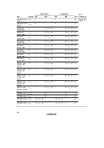
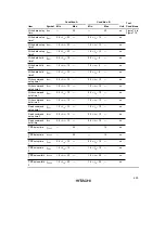
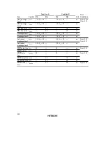
Condition A
Condition B
Test
Item
Symbol
Min
Max
Min
Max
Unit
Conditions
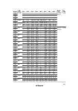
Address delay
time
t
AD
—
20
—
20
ns
Figure7.6 to
Figure7.19
Address setup
time 1
t
AS1
0.5
×
t
cyc
– 15
—
0.5
×
t
cyc
– 13
—
ns
Address setup
time 2
t
AS2
1.0
×
t
cyc
– 15
—
1.0
×
t
cyc
– 13
—
ns
Address setup
time 3
t
AS3
1.5
×
t
cyc
– 15
—
1.5
×
t
cyc
– 13
—
ns
Address setup
time 4
t
AS4
2.0
×
t
cyc
– 15
—
2.0
×
t
cyc
– 13
—
ns
Address hold
time 1
t
AH1
0.5
×
t
cyc
– 10
—
0.5
×
t
cyc
– 8
—
ns
Address hold
time 2
t
AH2
1.0
×
t
cyc
– 10
—
1.0
×
t
cyc
– 8
—
ns
Address hold
time 3
t
AH3
1.5
×
t
cyc
– 10
—
1.5
×
t
cyc
– 8
—
ns
CS
delay time 1
t
CSD1
—
20
—
15
ns
CS
delay time 2
t
CSD2
—
20
—
15
ns
CS
delay time 3
t
CSD3
—
20
—
20
ns
AS
delay time
t
ASD
—
20
—
15
ns
RD
delay time 1
t
RSD1
—
20
—
15
ns
RD
delay time 2
t
RSD2
—
20
—
15
ns
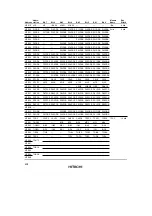
Read data setup
time 1
t
RDS1
15
—
15
—
ns
Read data setup
time 2
t
RDS2
15
—
15
—
ns
Содержание H8S/2670
Страница 5: ......
Страница 9: ......
Страница 199: ...182 ...
Страница 361: ...344 ...
Страница 393: ...376 ...
Страница 647: ...630 ...

