215
5.4.2
Register Configuration
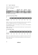
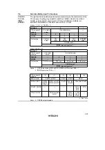
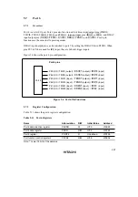
Table 5.6 shows the port 3 register configuration.
Table 5.6
Port 3 Registers
Name
Abbreviation
R/W
Initial Value
*
2
Address
*
1
Port 3 data direction register
P3DDR
W
H'00
H'FE22
Port 3 data register
P3DR
R/W
H'00
H'FF62
Port 3 register
PORT3
R
Undefined
H'FF52
Port 3 open drain control register
P3ODR
R/W
H'00
H'FE3C
Port function control register 2
PFCR2
R/W
H'0E
H'FE34
Notes: 1. Lower 16 bits of the address.
2. Value of bits 5 to 0.
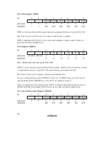
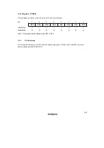
Port 3 Data Direction Register (P3DDR)
Bit
7
6
5
4
3
2
1
0
—
—
P35DDR P34DDR P33DDR P32DDR P31DDR P30DDR
Initial value
0
0
0
0
0
0
0
0
Read/Write
—
—
W
W
W
W
W
W
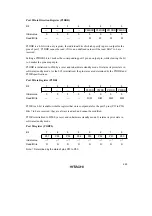
P3DDR is a 6-bit write-only register, the individual bits of which specify input or output for the
pins of port 3. P3DDR cannot be read; if it is, an undefined value will be read. Bits 7 and 6 are
reserved.
Setting a P3DDR bit to 1 makes the corresponding port 3 pin an output pin, while clearing the bit
to 0 makes the pin an input pin.
P3DDR is initialized to H'00 (bits 5 to 0) by a reset and in hardware standby mode. It retains its
prior state in software standby mode. As the SCI is initialized, the pin states are determined by the
P3DDR and P3DR specifications.
Содержание H8S/2670
Страница 5: ......
Страница 9: ......
Страница 199: ...182 ...
Страница 361: ...344 ...
Страница 393: ...376 ...
Страница 647: ...630 ...

