99
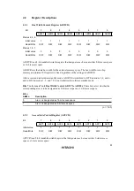
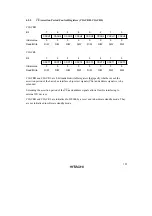
WTCRB
Bit
15
14
13
12
11
10
9
8
—
W32
W31
W30
—
W22
W21
W20
Initial value
0
1
1
1
0
1
1
1
Read/Write
R
R/W
R/W
R/W
R
R/W
R/W
R/W
Bit
7
6
5
4
3
2
1
0
—
W12
W11
W10
—
W02
W01
W00
Initial value
0
1
1
1
0
1
1
1
Read/Write
R
R/W
R/W
R/W
R
R/W
R/W
R/W
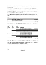
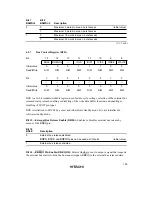
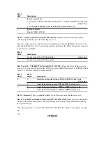
Bits 15, 11, 7, and 3—Reserved: These bits are always read as 0 and cannot be modified.
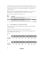
Bits 14 to 12, 10 to 8, 6 to 4, 2 to 0—Wait Control (Wn2, Wn1, Wn0): These bits select the
number of program wait states for areas designated as 3-state access space in ASTCR.
Wn2
Wn1
Wn0
Description
0
0
0
Program wait not inserted in area n external access
1
1 program wait state inserted in area n external access
1
0
2 program wait states inserted in area n external access
1
3 program wait states inserted in area n external access
1
0
0
4 program wait states inserted in area n external access
1
5 program wait states inserted in area n external access
1
0
6 program wait states inserted in area n external access
1
7 program wait states inserted in area n external access
(n = 7 to 0)
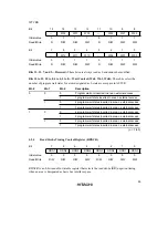
4.2.4
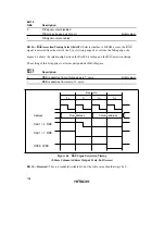
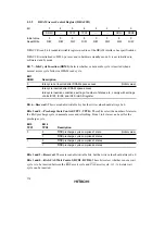
Read Strobe Timing Control Register (RDNCR)
Bit
7
6
5
4
3
2
1
0
RDN7
RDN6
RDN5
RDN4
RDN3
RDN2
RDN1
RDN0
Initial value
0
0
0
0
0
0
0
0
Read/Write
R/W
R/W
R/W
R/W
R/W
R/W
R/W
R/W
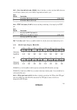
RDNCR is an 8-bit readable/writable register that selects the read strobe (
RD
) negation timing
when an area is designated as basic bus interface space.
Содержание H8S/2670
Страница 5: ......
Страница 9: ......
Страница 199: ...182 ...
Страница 361: ...344 ...
Страница 393: ...376 ...
Страница 647: ...630 ...


