


4
EtherCAT interface
48
Festo – GDCP-CMMP-M3/-M0-C-CO-EN – 1510b – English
4.3
Installing the EtherCAT interface in the controller
Note
Before performing mounting and installation work, observe the safety instructions in
the hardware description GDCP-CMMP-M3-HW-...
Use an appropriate Phillips screwdriver to remove the front cover over option slot Ext2 of the
CMMP-AS-...-M3 motor controller. The EtherCAT interface is now plugged into the open slot (Ext2) so
that the printed circuit board slides into the lateral guides of the slot. The interface is pushed in up to
the stop. Then screw the interface to the motor controller housing using the Phillips screw.
4.4
Pin allocation and cable specifications
RJ45 sockets
Function
[X1] (RJ45 socket on top)
Uplink to the master or a previous station of a series connection
(e.g. multiple motor controllers)
[X2] (RJ45 socket underneath)
End of a series connection or connection of additional downstream
stations
Tab. 4.2
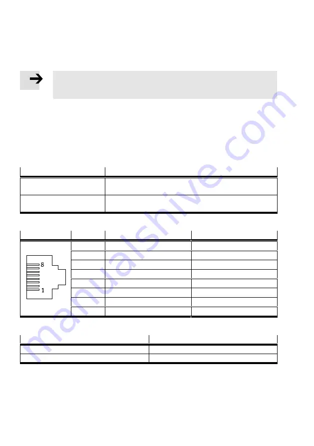
Design of plug connectors [X1] and [X2]
Pin
Specification
1
Receiver signal- (RX-)
Wire pair 3
2
Receiver (RX+)
Wire pair 3
3
Transmission signal- (TX-)
Wire pair 2
4
–
Wire pair 1
5
–
Wire pair 1
6
Transmission (TX+)
Wire pair 2
7
–
Wire pair 4
8
–
Wire pair 4
Tab. 4.3
Allocation of the plug connectors [X1] and [X2]
Value
Function
EtherCAT interface, signal level
0 … 2.5 V DC
EtherCAT interface, differential voltage
1.9 … 2.1 V DC
Tab. 4.4
EtherCAT interface specification
Type and design of cable
Shielded twisted-pair STP, Cat.5 cables must be used for cabling. Star and line topologies are suppor
ted. The network structure must conform to the 5-4-3 rule. A maximum of 10 hubs can be cabled in
series. The EtherCAT interface contains a hub. The total cable length is restricted to 100 m.


