


2
CANopen [X4]
12
Festo – GDCP-CMMP-M3/-M0-C-CO-EN – 1510b – English
120
Ω
120
Ω
CAN shield
CAN-GND
CAN-L
CAN-H
CAN shield
CAN-GND
CAN-L
CAN-H
CAN shield
CAN-GND
CAN-L
CAN-H
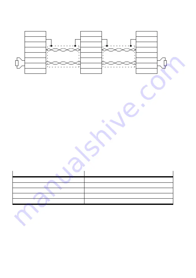
Fig. 2.1
Cabling example
–
The individual nodes of the network are connected point-to-point to each other, so the CAN cable is
looped from controller to controller (
–
A terminating resistor of exactly 120 Ω +/5 % must be available at both ends of the CAN cable.
Such a terminating resistor is often already integrated into CAN cards or PLCs, which must be taken
into account correspondingly.
–
A screened cable with precisely two twisted conductor pairs must be used for the cabling.
One twisted pair is used for connecting CAN-H and CAN-L. The conductors of the other pair are used
together for CAN-GND. The cable screening is connected to the CAN shield connection at all nodes.
(A table with the technical data of usable cables is located at the end of this chapter.)
–
The use of adapters is not recommended for CAN bus cabling. If this is unavoidable, then metallic
plug housings should be used to connect the cable screening.
–
To keep the disturbance coupling as low as possible, motor cables should not be laid parallel to
signal lines. Motor cables must conform to specifications. Motor cables must be correctly shielded
and earthed.
–
For additional information on design of trouble-free CAN bus cabling, refer to the Controller Area
Network protocol specification, Version 2.0 from Robert Bosch GmbH, 1991.
Characteristic
Value
Wire pairs
–
2
Wire cross section
[mm
2
]
0.22
Screening
–
Yes
Loop resistance
[Ω
/ m]
0.2
Surge impedance
[Ω
]
100…120
Tab. 2.2
Technical data, CAN bus cable


