COPYRIGHT © 2001 CANON INC. CANON CLC1000/1000S/3100 REV.2 MAY 2001 PRINTED IN JAPAN (IMPRIME AU JAPON)
3-43
3. OPERATION AND TIMING
a.
Shading Correction
The output of the CCD is not always the same for the following reasons; this is true even if the original
has a uniform density:
• The sensitivities of the pixels of the CCD are not the same.
• The degree of transmission of the lens differs between the center and the periphery.
• The intensity of the scanning lamp differs between the middle and the edges.
• The scanning lamp deteriorates.
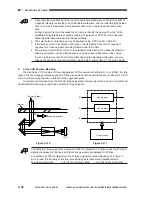
To compensate for the above discrepancies, the CLC1000 executes shading correction:
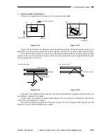
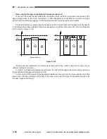
• Procedure of shading correction.
a)
The CCD reads the bar code under the
standard white plate and determines the
correction target value. (See Reference.)
Figure 3-307
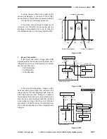
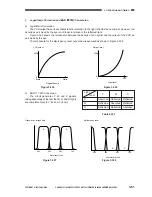
b)
The CCD measures the light reflected by the
standard white plate and generates data
representing the measurement.
Figure 3-308
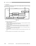
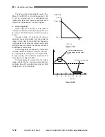
c)
The shading correction circuit compares the
measurement data (step b) against the target
value (step a) and stores the difference in
memory as the shading correction value.
The shading correction value is used to obtain
uniform data values when scanning originals.
Measurements are taken each time the Start
key is pressed.
Figure 3-309
Copyboard glass
Glass
Standard white plate
Bar code
Scanning lamp
Lens
CCD
Copyboard glass
Glass
Standard white plate
Bar code
Scanning lamp
Lens
CCD
Standard white plate
0
CCD output
255
Target value
(TRGT)
Characteristics before correction
Original density
White
Characteristics after correction
Measurement data
Содержание Vizcam 1000
Страница 12: ......
Страница 30: ......
Страница 44: ......
Страница 86: ......
Страница 254: ......
Страница 372: ......
Страница 374: ......
Страница 418: ......
Страница 438: ......
Страница 442: ......
Страница 754: ......
Страница 764: ......
Страница 766: ......
Страница 840: ...0501GR PRINTED IN JAPAN IMPRIME AU JAPON This publication is printed on 100 reprocessed paper...

