4. MECHANICAL SYSTEM
4-114
COPYRIGHT © 2001 CANON INC. CANON CLC1000/1000S/3100 REV.2 MAY 2001 PRINTED IN JAPAN (IMPRIME AU JAPON)
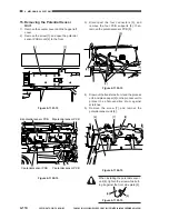
15. Removing the Potential Sensor
Unit
1)
Remove the counter cover and the hopper left
cover.
2)
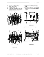
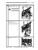
Remove the screw [1], and open the potential
sensor PCB mount [2] to the front.
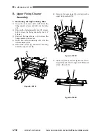
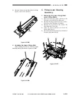
Figure 4-1101-15
Figure 4-1102-15
3)
Disconnect the four connectors [3], and
remove the four PCB supports [4]; then,
remove the potential sensor PCB [5].
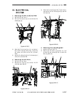
Figure 4-1103-15
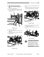
4)
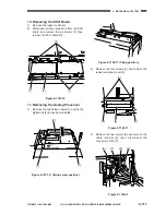
Draw out the transfer belt unit and the process
unit, and place paper [6] on the process unit to
protect the photosensitive drum against
scratches.
5)
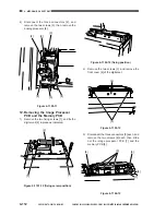
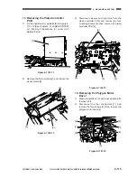
Remove the screw [7], and remove the
potential sensor unit [8].
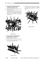
Figure 4-1104-15
When installing the potential sensor
unit [8], tighten the screw while butt-
ing it against the front side plate [9].
Figure 4-1105-15
[1]
[2]
Bk potential sensor PCB
M potential sensor PCB
C potential sensor PCB
Y potential sensor PCB
[5]
[4]
[3]
[4]
[6]
[7]
[8]
[9]
[8]
Содержание Vizcam 1000
Страница 12: ......
Страница 30: ......
Страница 44: ......
Страница 86: ......
Страница 254: ......
Страница 372: ......
Страница 374: ......
Страница 418: ......
Страница 438: ......
Страница 442: ......
Страница 754: ......
Страница 764: ......
Страница 766: ......
Страница 840: ...0501GR PRINTED IN JAPAN IMPRIME AU JAPON This publication is printed on 100 reprocessed paper...


