3. OPERATION AND TIMING
COPYRIGHT © 2001 CANON INC. CANON CLC1000/1000S/3100 REV.2 MAY 2001 PRINTED IN JAPAN (IMPRIME AU JAPON)
3-106
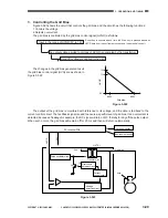
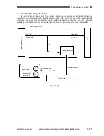
3. Controlling the DC Bias for Stray Toner Collection
Figure 3-531 shows the circuit that controls the DC bias for stray toner collection, and the circuit has the
following functions:
• Turns on and off the DC bias for stray toner collection.
• Executes constant current control.
The stray toner collection DB bias is turned on and off by the stray toner collection DC bias drive signal
(HVSRD) as follows:
HVSRD=1
The variable width pulse oscillator circuit turns ON, and pulse output is sent to the transformer.
The transformer is driven.
A DC bias is applied to the stray toner collection electrode.
The output of the stray toner collection DC bias is monitored with reference to its current value, and the
data is fed back to the variable width pulse oscillator circuit. This feedback ensures a constant level of DC
bias.
Figure 3-531
HVT3
24V
HVSRD
To stray toner collection electrode
DC controller PCB
Variable width pulse
oscillator circuit
Current
detection
circuit
24V
DC bias
Transformer
Содержание Vizcam 1000
Страница 12: ......
Страница 30: ......
Страница 44: ......
Страница 86: ......
Страница 254: ......
Страница 372: ......
Страница 374: ......
Страница 418: ......
Страница 438: ......
Страница 442: ......
Страница 754: ......
Страница 764: ......
Страница 766: ......
Страница 840: ...0501GR PRINTED IN JAPAN IMPRIME AU JAPON This publication is printed on 100 reprocessed paper...


