


4. MECHANICAL SYSTEM
4-68
COPYRIGHT © 2001 CANON INC. CANON CLC1000/1000S/3100 REV.2 MAY 2001 PRINTED IN JAPAN (IMPRIME AU JAPON)
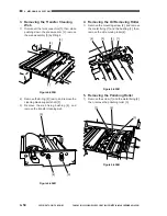
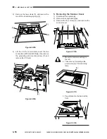
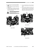
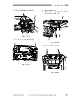
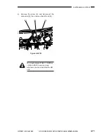
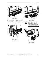
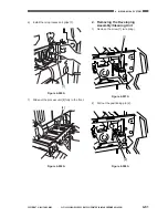
11) Shift the scanner unit to the left.
Figure 4-616B
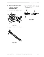
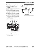
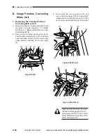
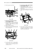
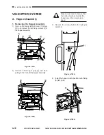
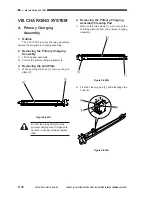
5. Removing the M Image Position
Correcting Mirror Unit
1)
Make preparations for parts associated with
the laser unit (See chapter 4. VI. LASER
SYSTEM, A-1. Making Preparation for Laser
Unit-Related Parts).
2)
Remove the laser cooling fan.
3)
Disconnect the three connectors [1], and
remove the two screws [2]; then, remove the
mirror cover (right) [3].
Figure 4-617B
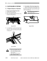
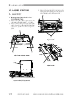
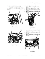
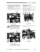
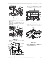
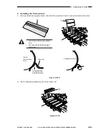
4)
As in the case of the Y image position
correcting mirror unit, remove the three
screws to remove the M image position
correcting mirror unit.
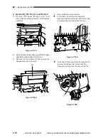
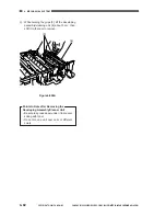
6. Removing the C/Bk Image Position
Correcting Mirror Unit
1)
Shift the scanner unit (See chapter 4. V.
EXPOSURE SYSTEM, B-4. Shifting the
Scanner Unit).
2)
Remove the two screws [1], and remove the
image position correcting mirror cover (left)
[2].
Figure 4-618B
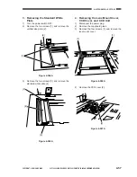
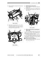
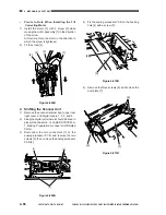
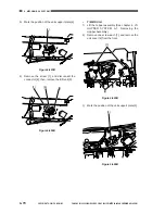
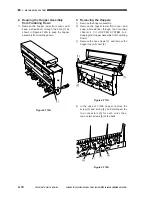
3)
Remove each of the image position correcting
mirror units (See chapter 4. VI. LASER
SYSTEM, B-5. Removing the Y/M Image
Position Correcting Mirror Unit).
[2]
[3]
[1]
[1]
[2]
[1]
[2]
Содержание Vizcam 1000
Страница 12: ......
Страница 30: ......
Страница 44: ......
Страница 86: ......
Страница 254: ......
Страница 372: ......
Страница 374: ......
Страница 418: ......
Страница 438: ......
Страница 442: ......
Страница 754: ......
Страница 764: ......
Страница 766: ......
Страница 840: ...0501GR PRINTED IN JAPAN IMPRIME AU JAPON This publication is printed on 100 reprocessed paper...


