
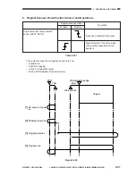


3. OPERATION AND TIMING
COPYRIGHT © 2001 CANON INC. CANON CLC1000/1000S/3100 REV.2 MAY 2001 PRINTED IN JAPAN (IMPRIME AU JAPON)
3-40
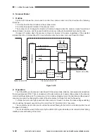
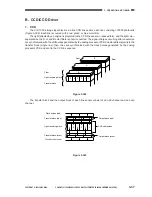
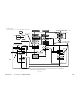
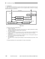
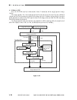
The above PCBs are organized as shown in Figure 3-305.
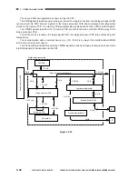
The RGB signals (simultaneously coming as a result of a single scan) from the analog processor PCB
are converted into YMC and text signals on the image processor PCB and compressed and temporarily
stored on the memory PCB. The memory PCB generates Bk signals based on these YMC and text signals.
The YMCBk signals read from the IP memory PCB are sent to the video controller PCB by way of the
image processor PCB.
The ED board A1 processes the image signals from the image processor PCB (area processing, text
composition).
The communication with an external device (e.g., IPU, IPU-II) is by way of the interface Board B1/B2
(which also corrects color space).
The Preview Monitor Board converts the YMCBk signals to which all image processing has been made
into RGB signals for transmission to the CRT.
Figure 3-305
Image processor PCB
ECO PCB
ED board A1
Y,M,C,Bk
R,G,B
R,G,B
R,G,B
R,G,B
R,G,B
Image processor motherboard
R,G,B
CRT
Digital image processing
Y,M,C,Bk
R,G,B
R,G,B
IP memory PCB
Interface motherboard
Preview Monitor Board
Interface Board B1/B2
IPU
Y,M,C,Bk
Y, M, C text
Y,M,C,Bk
Y,M,C,Bk
Y,M,C,Bk
Video controller
Analog processor PCB
Содержание Vizcam 1000
Страница 12: ......
Страница 30: ......
Страница 44: ......
Страница 86: ......
Страница 254: ......
Страница 372: ......
Страница 374: ......
Страница 418: ......
Страница 438: ......
Страница 442: ......
Страница 754: ......
Страница 764: ......
Страница 766: ......
Страница 840: ...0501GR PRINTED IN JAPAN IMPRIME AU JAPON This publication is printed on 100 reprocessed paper...


