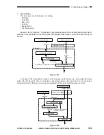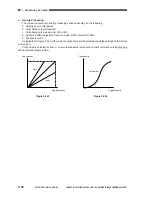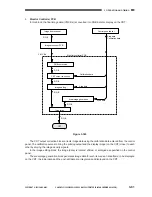
3. OPERATION AND TIMING
COPYRIGHT © 2001 CANON INC. CANON CLC1000/1000S/3100 REV.2 MAY 2001 PRINTED IN JAPAN (IMPRIME AU JAPON)
3-72
F. Laser Driver
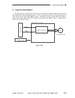
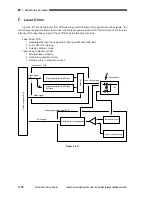
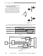
Figure 3-417 shows the laser driver PCB used to generate the laser drive signal from video signals. The
circuit drives the semiconductor laser units, and the laser power adjustment PCB monitors and controls the
intensity of the laser beam. Each of these PCBs has the following functions:
Laser Driver PCB
1 Generates the laser drive signals for 400 lines/200 lines/266 lines.
2 Turns ON/OFF the laser.
3 Selects activation mode.
Laser Power Adjustment PCB
1 Monitors laser intensity.
2 Generates activation current.
3 Detects errors in activation current.
Figure 3-417
+5V
Laser beam
Intensity monitor
Laser power setting
Activation current generation
Signal generation for 200 lines/
266 lines
8
Video signal
Signal generation for 400 lines
Laser drive signal
Error signal
Laser driver PCB
Laser power adjustment PCB
Mode signal
Video controller PCB
Selector
Содержание Vizcam 1000
Страница 12: ......
Страница 30: ......
Страница 44: ......
Страница 86: ......
Страница 254: ......
Страница 372: ......
Страница 374: ......
Страница 418: ......
Страница 438: ......
Страница 442: ......
Страница 754: ......
Страница 764: ......
Страница 766: ......
Страница 840: ...0501GR PRINTED IN JAPAN IMPRIME AU JAPON This publication is printed on 100 reprocessed paper...


