


7-36
COPYRIGHT © 2001 CANON INC. CANON CLC1000/1000S/3100 REV.2 MAY 2001 PRINTED IN JAPAN (IMPRIME AU JAPON)
7. TROUBLESHOOTING IMAGE FAULTS/MALFUNCTIONS
H. Laser Exposure System
1
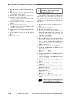
When Replacing the Laser
Unit
1) Perform laser focus adjustment.
2) Perform laser power adjustment.
3) Perform laser intensity adjustment.
2
When Replacing the Video
Controller PCB
Nothing in particular.
3
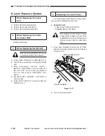
When Replacing the BD Unit
Before removing the BD unit, be sure
to mark its position with a scriber.
1) Using ‘FUNC > INSTALL’, set ‘IMG-REG’ to ‘0’.
2) Turn off the power switch, and replace the BD
unit.
3) After replacement, execute ‘FUNC >
INSTALL > REG-APER’ in service mode. (If a
BD error ‘E100’ occurs, check the position of
the unit, and execute ‘REG-APER’ once
again.)
4) Execute ‘FUNC > IMG-REG > AUTO-ADJ’ in
service mode.
5) Using ‘FUNC > INSTALL’ in service mode, set
‘IMG-REG’ to ‘1’.
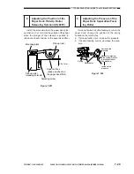
4
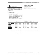
Adjusting the Laser Power
You must always adjust the laser power when-
ever you have replaced the laser unit.
a. Required Tools
• Laser Power Checker (FY9-4013)
• Digital Multimeter (CK-0436)
The output of the Laser Power
Checker may change over time; have
it calibrated once a year at the service
station using a special calibration
tool.
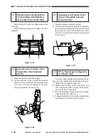
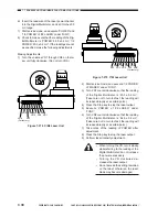
1) If you have replaced the laser unit for C/Bk,
position the analog processor unit as indicated
in Figure 7-271.
Claw
Screw
Analog processor unit
Copyboard glass
Figure 7-271
2) Turn on the power switch.
Содержание Vizcam 1000
Страница 12: ......
Страница 30: ......
Страница 44: ......
Страница 86: ......
Страница 254: ......
Страница 372: ......
Страница 374: ......
Страница 418: ......
Страница 438: ......
Страница 442: ......
Страница 754: ......
Страница 764: ......
Страница 766: ......
Страница 840: ...0501GR PRINTED IN JAPAN IMPRIME AU JAPON This publication is printed on 100 reprocessed paper...


