4. MECHANICAL SYSTEM
4-94
COPYRIGHT © 2001 CANON INC. CANON CLC1000/1000S/3100 REV.2 MAY 2001 PRINTED IN JAPAN (IMPRIME AU JAPON)
X. FIXING SYSTEM
A. Fixing Assembly
Maintenance work for parts associated with the
CLC1000’s fixing assembly may be performed
without removing the fixing assembly.
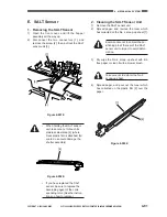
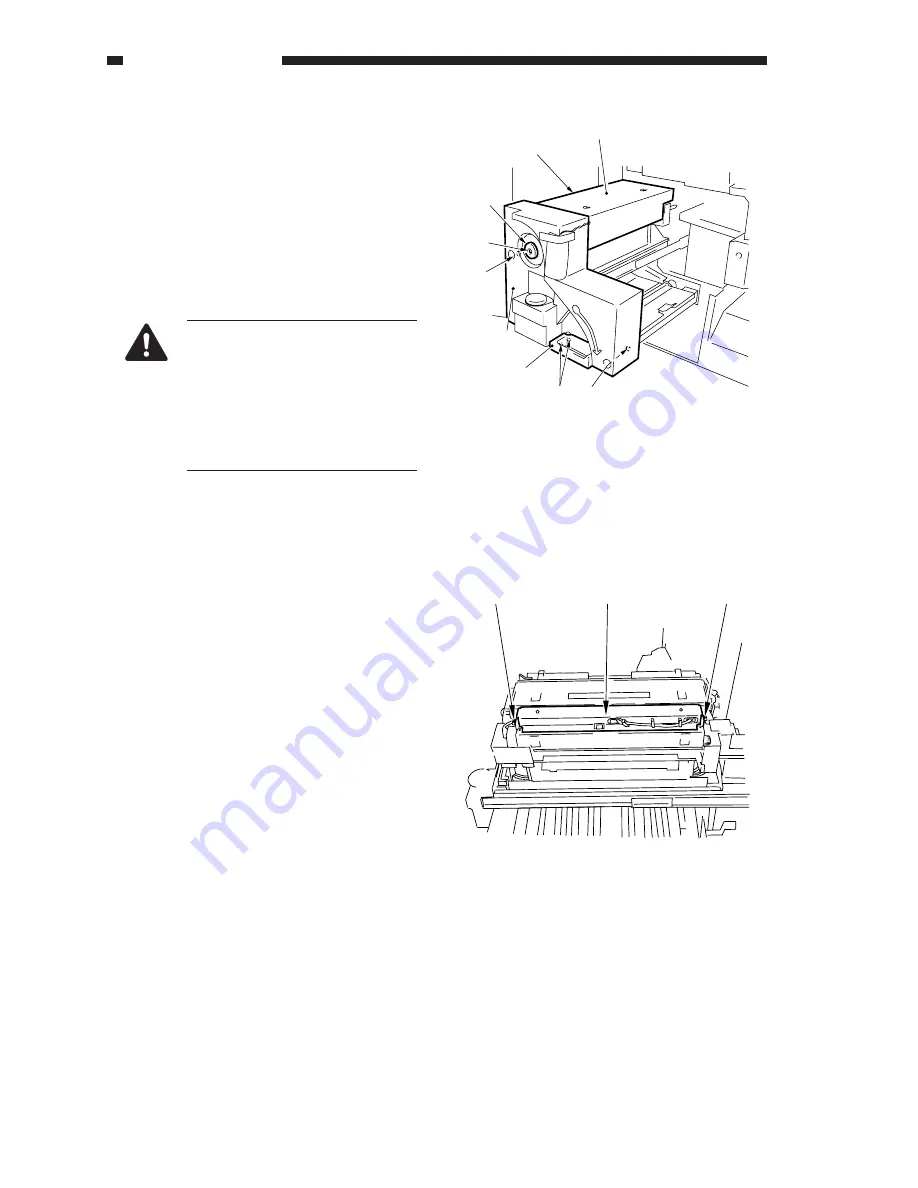
1. Removing the Fixing Assembly
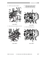
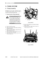
Figure 4-1001A
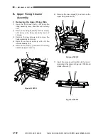
6)
Remove the screw [7], and remove the upper
fixing cover [8].
7)
Remove the two screws [9], and open the
upper fixing roller unit [10].
1)
Open the front cover (left).
2)
Remove the screw [1], and remove the fixing
assembly knob [2].
3)
Remove the two screws [3], and remove the
fixing assembly lever [4].
4)
Remove the two screws [5], and remove the
fixing assembly front cover [6].
5)
Open the external delivery unit and the
internal delivery unit.
Do not remove the fizmbly to re-
move such parts as the fixing roller.
The CLC1000’s fixing assembly is
independent from the lower oil pan;
to remove the fixing assembly, you
must draw the fixing oil collecting in
the upper oil pan to the oil bottle as
instructed below.
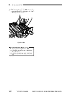
Figure 4-1002A
[7]
[8]
[2]
[1]
[5]
[6]
[4]
[5]
[3]
[9]
[9]
[10]
Содержание Vizcam 1000
Страница 12: ......
Страница 30: ......
Страница 44: ......
Страница 86: ......
Страница 254: ......
Страница 372: ......
Страница 374: ......
Страница 418: ......
Страница 438: ......
Страница 442: ......
Страница 754: ......
Страница 764: ......
Страница 766: ......
Страница 840: ...0501GR PRINTED IN JAPAN IMPRIME AU JAPON This publication is printed on 100 reprocessed paper...


