Anritsu BERTWave Series Скачать руководство пользователя страница 30


Chapter 1    Outline 

1-4 


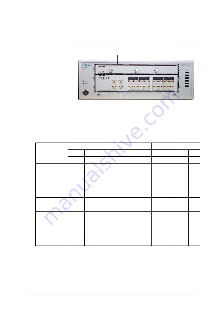
Figure 1.1.1-2    Front Panel of MP2110A 


The input connectors of the sampling oscilloscope can be selected by 
specifying the option.   

Table 1.1.1-1    Sampling Oscilloscope Input Connectors 


Channel A 

Channel B 

Channel C 

Channel D

Options Number Electrical  Optical Optical Electrical Optical Optical Optical Optical OpticalOptical


MMF*

1

SMF*

2

MMF*

1

SMF*

2

MMF*

1

  SMF*

2

 MMF*

1

SMF*

2

MP2110A-021 


MP2110A-022, 
MP2110A-032, 

MP2110A-042 


MP2110A-023, 
MP2110A-033, 

MP2110A-043 


MP2110A-025, 

MP2110A-035, 

MP2110A-045 


MP2110A-026, 
MP2110A-036, 

MP2110A-046 


MP2110A-030, 

MP2110A-040 


MP2110A-039, 

MP2110A-049 


*1:  For a multi-mode fiber 
*2:  For a single-mode fiber 

Note: 

MP2110A-022, 023, 025, 026, 040, 042, 043, 045, 046, 049 and 
MP2110A-030, 032, 033, 035, 036, 039 have different reference 
receiver properties (Bessel filter approximation property) of optical 
channel. MP2110A-030, 032, 033, 035, 036, and 039 are adjusted to 
have flat baseband properties. 

BERT: Bit Error Rate Tester 

Scope: Sampling Oscilloscope 

Содержание BERTWave Series

Страница 1: ...W3831AE 18 0 ANRITSU CORPORATION MP2110A BERTWave Operation Manual For safety and warning information please read this manual before attempting to use the equipment Keep this manual with the equipment...

Страница 2: ...in Manual The following safety symbols are used inside or on the equipment near operation locations to provide information about safety items and operation precautions Ensure that you clearly understa...

Страница 3: ...ock or causing damage to the internal components Only qualified service personnel with a knowledge of electrical fire and shock hazards should service this equipment This equipment cannot be repaired...

Страница 4: ...orrect manner If the cabinet is turned on its side etc it will be unstable and may be damaged if it falls over as a result of receiving a slight mechanical shock Always set up the equipment in a posit...

Страница 5: ...f this equipment external measuring instruments and DUT before connecting a coaxial cable Eliminate static electricity charged between the cores and outer conductors of an external device and the coax...

Страница 6: ...ponsible for lost data Pay careful attention to the following points Never remove the USB flash drive from the instrument while it is being accessed The USB flash drive may be damaged by static electr...

Страница 7: ...ent are not blocked or obstructed in any way Exercise care not to bang or shake the equipment whilst the power is on Never disconnect the mains power at the plug or cut the power at the breaker with t...

Страница 8: ...cause radio interference in which case the user may be required to take adequate measures Exposure to corrosive gases such as hydrogen sulfide sulfurous acid and hydrogen chloride will cause faults a...

Страница 9: ...the customer The fault is due to severe usage clearly exceeding normal usage The fault is due to improper or insufficient maintenance by the customer The fault is due to natural disaster including fir...

Страница 10: ...lectric charges or electromagnetic fields are present In places where abnormal power voltages high or low or instantaneous power failures occur In places where condensation occurs In the presence of l...

Страница 11: ...roduct s country of origin for re export from your country Before re exporting the product or manuals please contact us to confirm whether they are export controlled items or not When you dispose of e...

Страница 12: ...s with council directive 2012 19 EU the WEEE Directive in European Union For Products placed on the EU market after August 13 2005 please contact your local Anritsu representative at the end of the pr...

Страница 13: ...damages claimed by third parties arising out of or related to your use or inability to use this Software unless the damages are caused due to Anritsu s intentional or gross negligence Article 3 Limita...

Страница 14: ...violate any conditions described herein This EULA shall also be terminated immediately by Anritsu if there is any good reason that it is deemed difficult to continue this EULA such as your violation...

Страница 15: ...undergoing a thorough virus check Adding software Do not download or install software that has not been specifically recommended or licensed by Anritsu Network connections Ensure that the network has...

Страница 16: ...C 61000 4 3 EMF A IEC 61000 4 4 Burst B IEC 61000 4 5 Surge B IEC 61000 4 6 CRF A IEC 61000 4 11 V dip short B C Performance Criteria A The equipment shall continue to operate as intended during and a...

Страница 17: ...om the product description and documentation and what the user may reasonably expect from the equipment if used as intended C Temporary loss of function is allowed provided the function is self recove...

Страница 18: ...ontact Name Anritsu GmbH Address city Nemetschek Haus Konrad Zuse Platz 1 81829 M nchen Country Germany Name ANRITSU EMEA Ltd Address city 200 Capability Green Luton Bedfordshire LU1 3LU Country Unite...

Страница 19: ...on the following product s in accordance with the regulation to indicate that they conform to the EMC framework of Australia New Zealand RCM marking 1 Product Model Model MP2110A BERTWave 2 Applied S...

Страница 20: ...l The label shown on the left is attached to Anritsu products meeting our environmental standards Details about this label and the environmental standards are available on the Anritsu website at https...

Страница 21: ...the BERTWave status register structure and sample programs MX210001A Jitter Analysis Software Operation Manual M W3569AE This manual explains the operation method and remote control commands for the...

Страница 22: ...rement method Oscilloscope operation Windows file operations and the Windows Control Panel Manual Notation System The MP2110A BERTWave is referred to as the MP2110A in this manual The user interface s...

Страница 23: ...n 2 2 2 2 Part Names 2 5 2 3 Power Connection 2 13 2 4 Connecting Peripheral Devices 2 15 2 5 Connecting Remote Control Devices 2 16 2 6 Cautions on Handling Optical Fiber Cables 2 18 2 7 Connecting C...

Страница 24: ...How to Operate BERT 5 1 5 1 Procedure for Generating Pulse Signal 5 2 5 2 PPG ED Panel 5 3 5 3 Setting Restrictions 5 28 How to Operate Sampling Scope 6 1 Chapter 6 Measurement Procedure 6 2 6 1 Expl...

Страница 25: ...8 4 Displaying Software Version 8 8 8 5 Updating Software 8 9 8 6 Adding an Option License 8 10 8 7 System Recovery Function 8 12 8 8 Calibration 8 28 8 9 Storage 8 29 8 10 Transporting and Disposal 8...

Страница 26: ...VI...

Страница 27: ...al terms used in this manual 1 1 Introduction of BERTWave 1 2 1 1 1 MP2110A BERTWave 1 3 1 1 2 MP2100B BERTWave 1 8 1 2 Configuration 1 9 1 2 1 Standard Configuration 1 9 1 2 2 Options 1 12 1 2 3 Opti...

Страница 28: ...d The ED compares the received data bit string with the expected data a bit string and calculates the number of different bits bit error count It calculates the bit error rate from the number of recei...

Страница 29: ...s a measuring instrument that evaluates the electronic devices such as 100G bit Ethernet 100GbE OTU4 32G Fiber Channel 32GFC It performs the bit error rate test and waveform observation for the signal...

Страница 30: ...SMF 2 MP2110A 021 MP2110A 022 MP2110A 032 MP2110A 042 MP2110A 023 MP2110A 033 MP2110A 043 MP2110A 025 MP2110A 035 MP2110A 045 MP2110A 026 MP2110A 036 MP2110A 046 MP2110A 030 MP2110A 040 MP2110A 039 M...

Страница 31: ...n names are collectively called as follows BERT option MP2110A 011 MP2110A 012 and MP2110A 014 Scope option MP2110A 021 MP2110A 022 MP2110A 023 MP2110A 025 MP2110A 026 MP2110A 030 MP2110A 032 MP2110A...

Страница 32: ...Chapter 1 Outline 1 6 By installing MP2110A 095 PAM4 Analysis Software PAM4 waveform can be analyzed Figure 1 1 1 3 Example of PAM4 Waveform Analysis...

Страница 33: ...1 1 Introduction of BERTWave 1 7 1 Outline By installing MP2110A 096 Jitter Analysis Software jitter analysis result can be displayed Figure 1 1 1 4 Example of Jitter Analysis...

Страница 34: ...E using PPG and ED for 4 channels Figure 1 1 2 1 MP2100B External View MP2100B BERTWave is a space saving measuring instrument that can operate using the 12 1 inch touch panel The SFP slot and O E con...

Страница 35: ...BERTWave 1 Accessories POWER CORD 1 Contained in accessory box J1627A GND connection cable 1 Z1364A MX210000A BERTWave Control Software CD ROM 1 J0617B Replaceable optical connector FC PC 1 J1632A TER...

Страница 36: ...MP2110A 045 Ch B In SMF 1 MP2110A 026 MP2110A 036 MP2110A 046 Ch B In MMF 1 MP2110A 055 Optical SMF Data In Data Out 2 Table 1 2 1 3 Connection Destination and Quantity of J1632A Option Number Connect...

Страница 37: ...MP2110A 014 Ext Clk In Clk Out Sync Out 1 Data In 4 Data In 4 11 MP2110A 030 MP2110A 039 MP2110A 040 MP2110A 049 Trigger Clk In 1 MP2110A 021 Trigger Clk In Ch A In Ch B In 3 MP2110A 022 MP2110A 032 M...

Страница 38: ...options are included please refer to the ordering information on the Anritsu website https www anritsu com en us test measurement products mp2110a Number indicating function Anritsu management code 0...

Страница 39: ...Optical Scope for Multimode Baseband Flat 1 3 MP2110A 040 Quad Optical Scope for Singlemode 1 3 MP2110A 042 Dual Optical Scope 1 3 MP2110A 043 Optical and Single ended Electrical Scope 1 3 MP2110A 04...

Страница 40: ...5 FC UPC G0349S Optical Switch 2 4 GI62 5 SC UPC G0350F Programmable Optical Attenuator SM9 FC UPC G0350S Programmable Optical Attenuator SM9 SC UPC G0351F Programmable Optical Attenuator SM9 FC UPC...

Страница 41: ...al cable 0 8 m K connector J1510A Pick OFF Tee J1519A Optical Fiber Cord MM 12FIBER MPO 3M J1551A Coaxial skew match cable 0 8 m K connector J1632A Terminator J1681A MPO Loopback Cable J1682A MPO to F...

Страница 42: ...low residual jitter of 200 fs and rms typical value MP2110A 024 For sampling oscilloscope EYE analysis in short time using high speed sampling Compatibility of remote commands with previous Anritsu me...

Страница 43: ...through the transmission path which may be either coaxial cable or optical fiber In the communication where the bit rate is around 100 Gbit s the optical transceiver based on the multisource agreemen...

Страница 44: ...al power The following figure shows a connection example between the DUT and the measuring instruments when the DUT is the CFP4 module Figure 1 4 2 Connection Example of Receiver Sensitivity Measureme...

Страница 45: ...fore input only the optic of the wavelength to be measured using the optical demultiplexer or optical filter to MP2110A The following figure shows a connection example between the DUT and the measurin...

Страница 46: ...Bit Error Rate When the distribution of the noise voltage amplitude is assumed to follow a normal distribution the standard deviation is assumed to be n and the signal amplitude is s Bit errors occur...

Страница 47: ...hip between SNR and BER Bit Rate The Bit Rate is the speed at which the communications interface transmits and receives data It is expressed by the number of bits transmitted per second bit s or bps S...

Страница 48: ...bit error rates The center part of the graph is the center part of the eye pattern waveform and has small bit error rate This graph is called a Bathtub graph or Bathtub curve line from the form of the...

Страница 49: ...from the following equation DCD t2 t1 Bp 100 Where t1 Time at crossing point between 50 level of Eye Amplitude and rising waveform t2 Time at crossing point between 50 level of Eye Amplitude and fall...

Страница 50: ...d the waveform at the cross point level is measured and the result is plotted on the pattern location When the waveform time is slower than the clock the value is positive and when the waveform is fas...

Страница 51: ...5 6 the red line is the ideal symbol waveform and the blue line is the measured waveform with jitter Let t1 t2 t3 be the time of the blue line at the cross point and let the time differences between...

Страница 52: ...nt Dual Dirac Estimation is a method to estimate RJ and DJ using Dual Dirac function as the fitting curve of this histogram Figure 1 5 7 Histogram of Jitter with DJ The Dual Dirac distribution is expr...

Страница 53: ...tio 10log10 L1 LD L0 LD dB L1 1 Level mW L0 0 Level mW LD Level without optical input mW L0 L1 LD L1 LD L0 LD Figure 1 5 9 Extinction Ratio Measurement Level For the extinction ratio of PAM4 refer to...

Страница 54: ...Eye Heights of PAM4 Waveform When Sample Timing is Independent When Sample Timing is Track to Middle Eye Timing eye amplitude Upper and eye amplitude Lower are measured at the center position of Middl...

Страница 55: ...dth of PAM4 Waveform Eye Mask The Eye Mask is the boundary of the eye pattern waveform time and amplitude The value and waveform are specified by the communications standards Figure 1 5 13 Example of...

Страница 56: ...pattern created by superimposing the digital waveforms sampled at the same timing Eye pattern First measured waveform Second measured waveform Third measured waveform Fourth measured waveform Super i...

Страница 57: ...the center of each eye Eye Center and the centers of Upper Eye Middle Eye and Lower Eye Figure 1 5 15 PAM4 Eye Skews When Sample Timing is Independent When Sample Timing is Track to Middle Eye Timing...

Страница 58: ...in the time direction Eye Width t 2 3 2 t1 3 1 t1 Average time of first crossing point t 2 Average time of second crossing point 1 Standard deviation of first crossing point 2 Standard deviation of se...

Страница 59: ...itter RMS Standard deviation of histogram in time direction Figure 1 5 17 Jitter p p and Jitter RMS The jitter measured with the sampling oscilloscope is the combined values of jitters with various oc...

Страница 60: ...ak because its spreading is limited DDJ Data Dependant Jitter Jitter which is DJ and the occurrence amount depends on data DCD Duty Cycle Distortion Occurs with transmission reception circuit offset d...

Страница 61: ...nd the center of Middle Eye Level 1 Halfway of the center of Middle Eye and the center of Lower Eye Level 0 The center of Lower Eye Level Skews are differences between the positions measured at each l...

Страница 62: ...r 31 The Linearity in this case is 33 33 31 0 93 Mask Margin This is the margin between the waveform and the eye mask in mask test of eye pattern The margin in the amplitude direction is the ratio to...

Страница 63: ...evel Figure 1 5 21 0 Level 1 Level Eye Amplitude and Eye Height Outer ExR Outer Extinction Ratio Outer Extinction Ratio is the ratio of Level 3 and Level 0 of the PAM4 waveform and the calculation for...

Страница 64: ...the jitter time distribution PRBS Pseudo Random Bit Sequence PRBS is the abbreviation for pseudorandom bit sequence It is a bit string approximating actual communications data with a random distribut...

Страница 65: ...hange to the next level From 20 level of amplitude to 80 From 10 level of amplitude to 90 The Fall Time is the time taken for the signal level to change to the next level From 80 level of amplitude to...

Страница 66: ...V T P T 0 2 1 1 R V P 2 1 2 0 V t 0 V t V1 Figure 1 5 24 AC and DC Voltage Power Consumption In the circuit in Figure 1 5 24 the voltage V1 when the power P1 and P2 consumed by resistance R is equal i...

Страница 67: ...Third measurement waveform Fourth measurement waveform Superimposed waveform Figure 1 5 25 Drawing Method of Sampling Oscilloscope SNR Signal to Noise Ratio This is the ratio of the signal amplitude...

Страница 68: ...ated by the following formula For details refer to 95 8 5 2 TDEC measurement method of the IEEE 802 3 TDEC dB R Noise added at the receiver It is obtained from the measured results indicated by square...

Страница 69: ...sum of Insertion Error and Omission Error is referred to as the Total Error Signal 1 bits evaluated as 0 bits Omission Error Signal 0 bits evaluated as 1 bits Insertion Error Transition Time It is th...

Страница 70: ...MA log 10 0 dB Optical Modulation Amplitude 0 Vertical Eye Opening The histogram is measured at the center point between the cross points on the time axis OMA The upper and lower limits of the vertica...

Страница 71: ...bration CC Clock Count CFP C Form factor Pluggable Ch Channel CH Channel Clk Clock CPRI Common Public Radio Interface CRU Clock Recovery Unit DCD Duty Cycle Distortion DDJ Data Dependent Jitter DDPWS...

Страница 72: ...Negative NRZ Non Return Zero O E Optical to Electrical converter OMA Optical Modulation Amplitude OMI Omission OTU Optical Transport Unit Out Output PAM Pulse Amplitude Modulation PCML Positive Curren...

Страница 73: ...SSPRQ Short Stress Pattern Random Quaternary STM Synchronous Transfer Mode SYNC Synchronize Synchronization TDEC Transmitter and Dispersion Eye Closure TDECQ Transmitter and Dispersion Eye Closure for...

Страница 74: ...Chapter 1 Outline 1 48...

Страница 75: ...utions on Handling Optical Fiber Cables 2 18 2 7 Connecting Coaxial Cable 2 20 2 7 1 Notes on Coaxial Cable Connection 2 20 2 7 2 How to Discharge the Electrostatic Charges of the Coaxial Cable 2 21 2...

Страница 76: ...rting the BERTWave in future For repacking the MP2110A refer to 8 9 Transporting and Disposal The options listed in Table 1 2 2 1 are provided for the MP2110A Verify that the options purchased are ins...

Страница 77: ...from the top panel due to vibration or shock A fan is installed in the MP2110A to prevent the internal temperature from rising Install the MP2110A in a location with the vents at least 10 cm away from...

Страница 78: ...here these liquids may adhere In salty air or where chemically active gases sulfur dioxide hydrogen sulfide chlorine ammonia nitrogen oxide or hydrogen chloride etc are present Where toppling over may...

Страница 79: ...1 Front Panel Scope BERT Figure 2 2 1 2 Front Panel Scope CRU USB Connectors Scope Functional Ground Terminal Power Switch Remote Standby Functional Ground Terminal BERT USB Connectors Scope Function...

Страница 80: ...Panel of the clock recovery unit If neither BERT option nor MP2110A 055 is installed this slot is filled with a blank panel Remote Lights in green when MP2110A is under remote control Standby Lights i...

Страница 81: ...input of external clock 0 2 to 1 6 Vp p Sync Out Outputs the clock synchronized to PPG pattern VOH 0 2 to 0 05 V Sync Out Outputs the inverted clock synchronized to PPG pattern VOL 1 2 to 0 7 V Data O...

Страница 82: ...n Ch B In Scope Status Fail Fail Status Trigger Clk In 2Vp p Max Ch A In 2V Max Ch B In 2V Max Scope Status Fail CRU In 1Vp p Max CRU Out CRU Out CRU In Trigger Clk In 2Vp p Max Ch A In Ch B In Ch A I...

Страница 83: ...on and off the power but this is not an error Check the following items when the Status lamp is lit in orange Refer to Section 6 2 6 Time CRU Dialog Box for the operation method Specify the input tri...

Страница 84: ...peak MMF optical connector 10 dBm peak B 2 SMF 1260 to 1650 nm MMF 800 to 860 nm SMF optical connector 8 dBm peak MMF optical connector 10 dBm peak C 2 SMF 1260 to 1650 nm MMF 800 to 860 nm SMF optica...

Страница 85: ...are error is detected at startup The lamp may light in short time when turning on and off the power but this is not an error Check the following item when the Status lamp is lit in orange Refer to Sec...

Страница 86: ...ernal monitor Refer to 2 4 Connecting Peripheral Devices USB3 0 For connecting accessories including keyboard and mouse Ethernet For connecting to a PC or network to control MP2110A remotely Line Outp...

Страница 87: ...ower Requirements Power source Voltage range Frequency 100 Vac system 100 to 120 V 50 to 60 Hz 200 Vac system 200 to 240 V 50 to 60 Hz Operating voltage within the range of 10 to 15 from the rated vol...

Страница 88: ...isk of receiving a fatal electric shock In addition the peripheral devices connected to the MP2110A may be damaged Unless otherwise specified the signal connector ground terminal like an external cond...

Страница 89: ...e monitor is Connection via either HDMI or Display Port When connecting to an external monitor with the VGA connector use the HDMI to VGA conversion adapter Resolution 1280 800 or greater If the resol...

Страница 90: ...Ethernet Connect an Ethernet cable that is CAT 5 cable or newer to the Ethernet connector on the rear panel GPIB Connect the cable to the rear panel GPIB connector Figure 2 5 1 GPIB Cable Connection 1...

Страница 91: ...2 5 Connecting Remote Control Devices 2 17 2 Before Use Connect cables without forming loops Figure 2 5 2 GPIB Cable Connection 2 a Daisy Chain b Star c Loop...

Страница 92: ...N Do not pull the cable when removing the connector Doing so may break the optical fiber inside the cable or remove the cable sheath from the optical connector CAUTION Do not excessively bend fold or...

Страница 93: ...Be careful not to hit the end of an optical connector against anything hard such as the floor or a desk by dropping the optical fiber cable Doing so may damage the connector end and increase connectio...

Страница 94: ...of damage to the connector Tighten coaxial connectors to the correct torque 0 9 Nm If the coaxial connector is over tightened there is a risk of damage to the connector which may prevent disconnectio...

Страница 95: ...10A is charged electrostatically To prevent MP2110A from being damaged by ESD discharge the electrostatic charges of the coaxial cable by using the ESD Discharger which is an optional accessary of MP2...

Страница 96: ...power switch The power lamp lights green and the Windows start up begins 5 In 30 seconds the application window is displayed If the application window is not displayed refer to 2 9 3 Setting External...

Страница 97: ...otes If the power plug is removed while the panel access lamp is lit the data may not be saved correctly Depending on the type of data that was not saved correctly sometimes the equipment may not star...

Страница 98: ...2110A to work properly only when the factory settings for Windows have not been changed MP2110A operations are not guaranteed if program installation or update including Windows Update is performed Ch...

Страница 99: ...on Description Date and Time Change the date time and time zone as necessary Internet Time is set to off at factory shipment Operation may be affected if this setting is changed Display Intel HD Graph...

Страница 100: ...Win10 The setting method differs depending on the operating system For WES7 1 Connect the external monitor to the monitor connector on the rear panel of the MP2110A 2 Set the MP2110A and monitor power...

Страница 101: ...rs Click Keep changes 10 Click on the task bar 11 When the external monitor resolution is set to 1280 800 click System Menu Dock Undock to fix the application window at top left of the screen refer to...

Страница 102: ...n the rear panel of the MP2110A 2 Set the MP2110A and monitor power to On 3 Click System Menu 4 Click Minimize 5 Right click on desk top 6 Click Display Settings 7 Change the external monitor resoluti...

Страница 103: ...Click Keep changes 9 Click on the task bar 10 When the external monitor resolution is set to 1280 800 click System Menu Dock Undock to fix the application window at top left of the screen refer to 4 3...

Страница 104: ...in test circuit After confirming that both the MP2110A and DUT are grounded use coaxial cables to connect them NEVER connect the MP2110A and DUT without grounding otherwise electrostatic discharge may...

Страница 105: ...f the coaxial cable connected to the input connector or bring it into contact with metal Doing so may damage the input circuit of the MP2110A CAUTION Do not touch the core conductor to the metal when...

Страница 106: ...input connector of the MP2110A connect an attenuator that can protect the MP2110A without affecting measurement results An attenuator with a bandwidth of 40 GHz or more is recommended The outer condu...

Страница 107: ...to the MP2110A Use coaxial cables when connecting On the contrary disconnect the coaxial cables between external devices and the MP2110A before turning off the external devices Figure 2 10 1 1 Example...

Страница 108: ...T Failure to do so may cause damage to MP2110A due to a voltage exceeding a rated value Review the ground wiring by for example changing the location of the DUT s ground wire connected to MP2110A so t...

Страница 109: ...ions to check the observed waveform for surge voltage exceeding the rated voltage There is a risk of damage if a voltage exceeding the rated voltage is generated Turning On Off the DUT power Outputtin...

Страница 110: ...C voltage is impressed Only switch DC power sources ON and OFF when all equipment connections have been completed Figure 2 10 2 1 Bias T Connection Example Recommended procedures Measurement Preparati...

Страница 111: ...the MP2110A and all equipment or change the DUT connections Since even unforeseen fluctuations in DC voltage and load open or short circuits at the MP2110A output side and changes caused by using a hi...

Страница 112: ...f Windows For WES7 1 Click Start Control Panel from the Windows menu bar hidden in the lower part of the screen 2 Click System and Security Action Center 3 Click Security and confirm security measures...

Страница 113: ...art Control Panel from the Windows menu bar hidden in the lower part of the screen 2 Click System and Security Windows Firewall to show Windows Firewall window Note Depending on when MP2110A was shipp...

Страница 114: ...ndows firewall On Off settings can be changed Use MP2110A with the following checkboxes Off unchecked Block all incoming connections including those in the list of allowed programs Notify me when Wind...

Страница 115: ...t to operate properly it is necessary to set as allowed programs those that enable external communication from MP2110A Note Depending on when MP2110A was released factory default setting for allowed p...

Страница 116: ...where programs allowed through Windows firewall can be confirmed Confirm if MX210000A is found and set to On checked under Allowed programs and features When no such information is displayed it is ne...

Страница 117: ...o add MX210000A when it is not registered WES7 1 Use the mouse to click Allow another program found in Allowed Programs window Figure 2 11 1 5 Allowed Programs Window 2 In Add a Program window select...

Страница 118: ...Chapter 2 Before Use 2 44 3 MX210000A is added to Allowed programs and features Confirm if MX210000A is found and set to On checked Figure 2 11 1 7 Allowed Programs Window...

Страница 119: ...10A was shipped factory default setting of Windows firewall might be set to On 3 Click Turn Windows Defender Firewall on or off found in left side of Windows Defender Firewall window Figure 2 11 1 8 W...

Страница 120: ...llow an app or feature through Windows Defender Firewall found in left side of Windows Defender Firewall window Figure 2 11 1 10 Windows Defender Firewall Window 2 Allowed apps window will be shown wh...

Страница 121: ...re to add MX210000A Main Application when it is not registered Win10 1 Use the mouse to click Allow another apps found in Allowed apps window Figure 2 11 1 12 Allowed apps Window 2 Add an app window i...

Страница 122: ...dd an app is shown Select C Program Files Anritsu MP2100A MX210000A MainApp exe and click Open Figure 2 11 1 14 Browse Window of Add an app 4 In Add an app window select MX210000A Main Application and...

Страница 123: ...s Security Measures 2 49 2 Before Use 5 MX210000A Main Application is added to Allowed apps and features Confirm if MX210000A Main Application is found and set to On checked Figure 2 11 1 16 Allowed a...

Страница 124: ...dates in Windows Instead it is recommended to manually check for download and install new updates on a periodic basis avoiding the operating hours of MP2110A Windows Update setting and execution For W...

Страница 125: ...ates then click OK Figure 2 11 2 2 Change settings Window 5 To check for newly available update programs manual update click Check for updates in Windows Update window Figure 2 11 2 3 Windows Update W...

Страница 126: ...Update window 3 To turn off automatic updates select Windows Update found in left side of Windows Update window and then click Advanced options Figure 2 11 2 4 Windows Update Window 4 Advanced option...

Страница 127: ...check for newly available update programs manual update click Check for updates in Windows Update window Figure 2 11 2 6 Windows Update Window manual update 6 When a new update program is found downl...

Страница 128: ...basis avoiding the operating hours of MP2110A The antivirus software that checked operation in MP2110A is shown below Trend Micro OfficeScan XG Notes Refer to the antivirus software operation manual...

Страница 129: ...tical level input to the DUT such as the receiver sensibility measurement connect other measurement instruments such as optical attenuator When using the MP2110A 030 039 040 or 049 option replace the...

Страница 130: ...t it to the Data Out connector of PPG1 Also connect the coaxial terminator which is attached to the MP2110A standard configuration to the Data Out connector 2 Connect the DUT output connectors to ED1...

Страница 131: ...ate BERT for details of the operation method 5 Click the PPG Data XData button and set the display to ON Check the following items The Output lamp 1 on the BERT panel is lit Refer to Figure 2 2 1 3 In...

Страница 132: ...coaxial cables If the DUT has only one input connector connect it to the PPG1 Data Out Also connect the coaxial terminator included as a standard accessory to the Data Out 2 Connect the Clk Out or Sy...

Страница 133: ...Refer to Chapter 5 How to Operate BERT for details of the operation method 6 Click the PPG Data XData button and set the display to ON Check the following items The Output lamp 1 on the BERT panel is...

Страница 134: ...hapter 6 How to Operate Sampling Scope for details of the operation method 10 Click Ch A and Ch B 11 Click the Control Ch button and set the display to All 12 Click Sampling and you will see that Samp...

Страница 135: ...input connector connect it to the PPG1 Data Out Also connect the coaxial terminator included as a standard accessory to the Data Out 2 Connect the DUT optical output connector to Ch B In using an opt...

Страница 136: ...ED Ch1 5 Set Clk Out Bit Rate PPG Amplitude and Test Pattern Refer to Chapter 5 How to Operate BERT for details of the operation method 6 Click the PPG Data XData button and set the display to ON Che...

Страница 137: ...pe Refer to Chapter 6 How to Operate Sampling Scope for details of the operation method 8 Click Time 9 Click Rate and set Tracking 10 Click Amplitude O E 11 Click O E and set Input Connector Wavelengt...

Страница 138: ...r pairs of transmitters and receivers With the MP2110A 014 the CFP4 module bit error rate can be measured for four channels simultaneously If using a separate CFP4 for transmission in addition to the...

Страница 139: ...e 3 11 3 Measurement Examples Figure 3 3 1 Simultaneously Measuring Bit Error Rate for 4 Channels MP2110A 014 Optical Power Programmable Optical Fiber Optical Coupler or Optical Switch TX1 to TX4 Data...

Страница 140: ...tput connectors and ED1 ED4 Data In connectors using coaxial cables 6 Connect the optical output connector of the CFP4 for transmission to the input connector of the optical attenuator using an optica...

Страница 141: ...G ED Ch1 11 Set Bit Rate PPG Amplitude ED Input Condition and Test Pattern Refer to Chapter 5 How to Operate BERT for details of the operation method 12 Set Gating 13 Change the color of the character...

Страница 142: ...ing items The Output lamps 1 to 4 on the BERT panel are lit Refer to Figure 2 2 1 3 In the application window the SYNC Loss and Error indicators are off 16 Change the color of the characters on the bu...

Страница 143: ...1 4 3 4 Initialize 4 12 4 3 5 Panel Lock 4 12 4 3 6 Local Panel Unlock 4 12 4 3 7 Before Use 4 13 4 3 8 Minimize 4 14 4 3 9 Dock Undock 4 14 4 3 10 Remote Control 4 15 4 3 11 System Information 4 17 4...

Страница 144: ...ames of Application Window Elements The elements that are set as common in the channels other than Ch 1 are displayed by light blue characters System Menu All Measurements Stop All Start All Channels...

Страница 145: ...System Menu Provides the following menu option buttons Save Open Screen Copy Initialize Panel Lock Local Panel Unlock Before Use Minimize Dock Undock Remote Control System Information Exit Function me...

Страница 146: ...utton Option Number MP2110A 011 MP2110A 012 MP2110A 014 MP2110A 021 022 023 025 026 030 032 033 035 036 039 040 042 043 045 046 049 MP2110A 055 PPG ED Ch1 PPG ED Ch2 PPG ED Ch3 PPG ED Ch4 Scope CRU Di...

Страница 147: ...e 4 2 1 is displayed Click the right and left arrow keys and select the line to change the value Click the up and down arrow keys or turn the rotary knob to change the value Figure 4 2 1 Arrow Key Ent...

Страница 148: ...ey entry panel display button and then the arrow key entry panel as shown in Figure 4 2 1 is displayed Figure 4 2 2 Numeric Value Entry Panel Table 4 2 2 lists the keys on the keyboard corresponding t...

Страница 149: ...Keyboard screen Figure 4 2 3 click keys to enter an alphanumeric string If you click Shift or Caps once all keys are locked To unlock them click Shift or Caps again Figure 4 2 3 Software Keyboard Fig...

Страница 150: ...mote display Local Panel Unlock Playing back the video of countermeasure against static electricity Before Use Minimizing screen display Minimize Setting the application window display position Dock U...

Страница 151: ...Result Measurement results 4 The file name is displayed To edit the displayed default file name click Screen Keyboard 5 In the Keyboard screen edit the file name 6 To save to a file click OK To cancel...

Страница 152: ...panel 2 Select the target module form the following PPG ED Ch 1 PPG ED Ch 2 PPG ED Ch 3 PPG ED Ch 4 Scope All Setups The displayed module varies with options 3 The file selection screen is displayed 4...

Страница 153: ...utton 4 To input the file name click Screen Keyboard to set the file name 5 To overwrite an existing file click the file name in the File List area 6 Click OK to save a screenshot as a file When overw...

Страница 154: ...ions at other than System Menu is called panel locking 1 Click Panel Lock to lock the panel 2 The screen elements other than System Menu status indicators and date and time display are shaded Even if...

Страница 155: ...measure against static electricity Click Before Use Other window is displayed and the video of countermeasure against static electricity is played back in the window The playback time is about 1 minut...

Страница 156: ...n click MX210000A on the task bar 4 3 9 Dock Undock Changing the window display method Click Dock Undock At Dock the window is fixed at the upper left of the screen and the window cannot be moved This...

Страница 157: ...lick the GPIB Address text box A dialog box for inputting the address is displayed 2 Enter the GPIB address in the range of 0 to 30 3 To complete the setting click OK To cancel the setting click Cance...

Страница 158: ...click Properties 6 In the Internet Protocol Version 4 TCP IPv4 Properties dialog box configure the settings To automatically obtain an IP address of Local Area Connection using DHCP click Obtain an IP...

Страница 159: ...formation dialog box appears Figure 4 3 11 1 System Information Dialog Box Click Save To Clipboard to copy the system information to the Windows clipboard Click Save To File to open the Save dialog bo...

Страница 160: ...see the dialog box asking if you want to terminate the application 2 To terminate the application click Yes To cancel the application termination click No To restart the application Double click the M...

Страница 161: ...on turn green and then the Output status indicator turns green Figure 4 4 1 All Outputs Button Signals are output from all channels of PPG To stop the signal output from the PPG 1 Click off at All Ou...

Страница 162: ...to four channels and sample waveform data for up to four channels simultaneously To start simultaneous measurement click the key shown in Figure 4 5 1 The Measure status indicator turns green To stop...

Страница 163: ...To apply the PPG and ED settings for Ch1 to other channels click on In this state altering settings for Ch1 also alters the settings for other channels Figure 4 6 1 Ch Tracking The following settings...

Страница 164: ...e 4 7 2 All BER Results Display Table 4 7 1 All BER Measurements Buttons Name Description Start Starts BER measurement for all channels The sampling oscilloscope measurement is not started Stop Stops...

Страница 165: ...cate the status Table 4 8 1 Status Indicators Indicator Status Remote Turns blue when the MP2110A is being remotely controlled Measure Turns green when measuring bit error rate or acquiring waveform d...

Страница 166: ...Chapter 4 Screen Operation 4 24...

Страница 167: ...l 5 3 5 2 1 Setting Reference Clock 5 7 5 2 2 Setting Bit Rate 5 8 5 2 3 Setting Patterns 5 10 5 2 4 Setting Output Waveform 5 13 5 2 5 Setting Sync Out 5 14 5 2 6 Setting Clk Out 5 16 5 2 7 Inserting...

Страница 168: ...lock to Ext Clk In connector Set the pattern Set the bit rate and offset Turn Data XData on End Is the external clock used No Yes No Yes Set the bit rate standard Set positive logic or negative logic...

Страница 169: ...ays the following panel The elements that are set as common in the channels other than Ch 1 are displayed by the light blue characters Figure 5 2 1 PPG ED Settings Panel Figure 5 2 2 shows the bit rat...

Страница 170: ...p Result is clicked the panel display is changed to the panel shown in Figure 5 2 3 And when Setup Result is clicked again the panel display is changed to the panel shown in Figure 5 2 1 Figure 5 2 3...

Страница 171: ...synchronization status Red Reference clock cannot be detected Yellow Reference clock was detected but is not synchronized with pattern data Green Reference clock is synchronized with pattern data PPG...

Страница 172: ...ror measurement from the time set at Gating Start Stop Stops starts bit error rate measurement History Reset Deletes the history displays of Sync Loss and Error Reference CLK 1 Selects the clock to be...

Страница 173: ...ion Frequency of Clock Input to Ext Clk In MHz Internal Use the internal clock based on the internal 10 MHz oscillator Ext Clk 1 16 Use the external clock input from the Ext Clk In connector When the...

Страница 174: ...ing on whether MP2110A 093 is added or not Figure 5 2 2 1 Bit Rate Standard Value Dialog Box Without MP2110A 093 Figure 5 2 2 2 Bit Rate Standard Value Dialog Box With MP2110A 093 2 Click the bit rate...

Страница 175: ...of MP2110A and the DUTs click the Ext ATT text box and input the attenuation The amplitude voltage after passing through the attenuator is displayed CAUTION When inserting attenuator at both the Data...

Страница 176: ...ven stage flip flop and an Exclusive OR circuit A signal of the sixth and seventh stages of the shift register are input to the Exclusive OR and the output of the Exclusive OR is input to the shift re...

Страница 177: ...e pattern of which the clock frequency is divided in half is output from the Data Out connector and Data Out connector Figure 5 2 3 2 Relationship between Data and Clock when 1 2 Clock Pattern is set...

Страница 178: ...the Data connector goes Low when the data is 1 Figure 5 2 3 4 Relationship between Logic Setting and Output Voltage Waveform at Connector Set the pattern using the following procedure 1 Click the but...

Страница 179: ...d correctly if a coaxial cable with another impedance is used or if the impedance of the DUT is not 50 The amplitude of signal output to the Data Out and Data Out connectors is 0 1 to 0 8 Vp p Check t...

Страница 180: ...Sync at Sync Out and connect the Sync Out connector and the Trigger Clk In connector of the sampling oscilloscope using a coaxial cable Figure 5 2 5 1 Correspondence between Sync Output Setting and O...

Страница 181: ...8 s 2 34 s 1 27 s 1 17 s PRBS 2 23 1 838 9 s 598 1 s 325 4 s 299 1 s PRBS 2 31 1 214 7 ms 153 1 ms 83 3 ms 76 6 ms CAUTION The impedance of the Sync Out connector is 50 Measurement may not be performe...

Страница 182: ...xial cable For MP2110A 093 the clock output division rate is automatically changed according to the bit rate 24 3 to 28 2 Gbit s 1 4Clock 9 5 to 14 2 Gbit s 1 2Clock For MP2110A 014 the clock source o...

Страница 183: ...irming whether to detect the bit error at the ED The number of bit errors to be inserted at one time is determined according to the bit rate 24 3 to 28 2 Gbit s 20 bit 9 5 to 14 2 Gbit s 8 bit Inserti...

Страница 184: ...T panel is as shown below Figure 5 2 8 1 Input Connector Block Diagram CAUTION The impedance of the electrical input connector is 50 Measurement may not be performed correctly if a coaxial cable with...

Страница 185: ...ttenuator The threshold voltage calculated to the input voltage of the attenuator is displayed The calculation formula is as follows Calculated Threshold Voltage Threshold Voltage 10 attenuation 20 CA...

Страница 186: ...the connector and the DC component when inputting the 1 2V LVCMOS signal to the Data In connector and Data In connector is shown below Set the threshold level to the waveform excepting the DC compone...

Страница 187: ...button and select the standard 3 Click the Test Pattern button and select the pattern Set the same pattern of the PPG 4 Set Logic to POS or NEG 5 Click the ED Input Condition button 6 Select the conn...

Страница 188: ...timed Performs measurement until ER Result button display becomes Stop The bit errors are accumulated The following figure shows the relationship between the Gating Cycle setting and the change in the...

Страница 189: ...asurement method as follows Repeat Single Untimed 2 When Gating Cycle is Repeat or Single click the text box under the Gating Cycle and enter the numeric value The measurement cycle can be set from 1...

Страница 190: ...by the DUT matches the Test Pattern for the error detector The Logic POS and NEG settings are correct A suitable threshold voltage has been set for the signal input to the Data In connector and the Da...

Страница 191: ...rors are displayed from 0 to 9999999 or from 1 0000E07 to 9 9999E17 CC The received bit count is displayed from 0 to 9999999 or from 1 0000E07 to 9 9999E17 FREQ kHz Clock frequency calculated by the r...

Страница 192: ...ttern Figure 5 2 11 1 Text File Example Figure 5 2 11 2 CSV File Example Anritsu MP2110A 01 00 TXT Pattern PRBS2 9 1 Option 12 21 24 93 Start 2017 03 27 15 46 16 End 2017 03 27 15 46 26 Total ER 0 000...

Страница 193: ...ed file name click OK 6 Click the right button of the text box when editing the file name The software keyboard is displayed 7 Input the file name 8 When changing the file name click OK and when cance...

Страница 194: ...e Pattern Sync is disabled due to the hardware restrictions The setting item can be selected but PPG 1 8 Clock is output under this condition When the following conditions are met no signal is output...

Страница 195: ...rrent 6 60 6 3 3 Adjusting values for changing the wavelength bands 6 60 6 3 4 Performing Self Test 6 62 Setting CRU 6 63 6 4 Setting Rate 6 66 6 5 6 5 1 Setting Symbol Rate 6 67 6 5 2 Setting Clock R...

Страница 196: ...or D of the Scope panel Set Symbol Rate Calibration required Perform calibration Set to Sampling mode Set Clock Frequency or Clock Divide ratio Eye mode Set pattern length Sets data acquired method Tu...

Страница 197: ...not displayed The CRU dialog box is displayed instead When you click Setup Measure Amplitude O E or Time CRU the corresponding dialog box is displayed Scale self adjust Graph display mode setting Hist...

Страница 198: ...not Time CRU but Time is displayed When Channel Math in Amplitude O E dialog box is On Scale Offset cannot be operated Trace switch buttons Set the trace s to display on the graph and the channel to c...

Страница 199: ...by Sampling Auto Scale and Clear Display All All channels Single Active channel only When Control Ch is set to Single the buttons effective only for the active channel are indicated by the same color...

Страница 200: ...CRU Dialog Box Figure 6 2 1 4 How Setting Items Look When Control Ch is Set to Single Even if Control Ch is set to All the items indicated by the active channel color can be set separately Note If the...

Страница 201: ...display area Channel A Level scale Channel B Top level Time scale Channel A GND level Channel B GND level Precision trigger status Channel B Optical connector type Channel A Optical connector type On...

Страница 202: ...al input power exceeds the upper limit An index of the peak power level is 2200 W for SM 2600 W for MP2110A x30 and x40 and 3200 W for MM Clipped A clipped waveform is displayed because the amplitude...

Страница 203: ...7 Quick Menu Graph display mode setting There are three graph display modes Overlap Overlaps traces of multiple channels Single Displays only the trace of the active channel Tile Displays four trace...

Страница 204: ...on Result Window Figure 6 2 1 9 Result Window Number of measurement items is from five to eight Figure 6 2 1 10 Result Window Number of measurement items is nine or more Waveform display area Measurem...

Страница 205: ...s Scope Result dialog box and the waveform is displayed larger Figure 6 2 1 11 Enlarging Display of Result Window Number of measurement items is nine or more Click Screen Copy in the Scope Result dial...

Страница 206: ...a measurement item the letter turns blue and the measurement area is displayed with a yellow dotted line in the window When clicking the measurement item again the display of the measurement area disa...

Страница 207: ...Level CAL Red There is a difference of 5 0 C or more from the calibration temperature Calibrate the level according to 6 3 1 Calibrating Level 26G CRU Unlock Orange MP2110A 054 Clock Recovery Electri...

Страница 208: ...lt Window Graph Display When Advanced Jitter is set to Sampling Mode in the Setup dialog box the following buttons in the Result window cannot be operated Control Ch Auto Scale Clear Display Quick Men...

Страница 209: ...clicked Graph selection buttons appear and the graph to display can be selected When Sampling Mode is Eye the active channel is displayed on the button Figure 6 2 2 3 Examples of Graph selection butto...

Страница 210: ...Chapter 6 How to Operate Sampling Scope 6 16 Figure 6 2 2 4 Switching Graph Display...

Страница 211: ...the histogram of the active channel is displayed Figure 6 2 2 1 1 TJ Histogram Table 6 2 2 1 1 TJ Histogram Item Name Description Estimate RJ DJ Histogram Appears when Sampling Mode is set to Eye Swit...

Страница 212: ...opening The red line and eye opening are displayed at the location of specified BER The eye opening is displayed at the measurement result area TD data BER curve line measured with Scope Dual Dirac BE...

Страница 213: ...h the type of measurement edge All Fall or Rise is displayed in the graph name The measurement edge type is set on the Algorithm tab of the Jitter Measure dialog box TJ Histogram Click TJ Histogram on...

Страница 214: ...e red line and eye opening are displayed at the location of specified BER The eye opening is displayed at the measurement result area TD data BER curve line measured with Scope Dual Dirac BER Bathtub...

Страница 215: ...am is set to ON histogram of RJ approximated by dual Dirac function is displayed in yellow and amplitude of PJ is displayed in red line Figure 6 2 2 2 3 RJ PJ Histogram Table 6 2 2 2 3 RJ PJ Histogram...

Страница 216: ...ck Composite Histogram on the Graph selection buttons TJ RJ PJ and DDJ histograms are displayed Figure 6 2 2 2 4 Composite Histogram Table 6 2 2 2 4 Composite Histogram Item Name Description TJ Sample...

Страница 217: ...ge Figure 6 2 2 2 5 DDJ Histogram Table 6 2 2 2 5 DDJ Histogram Item Name Description All Edges When the button display is ON the histogram is displayed Rise Edges Fall Edges All Samples The number of...

Страница 218: ...PJ vs Frequency on the Graph selection buttons spectrum of jitter is displayed Figure 6 2 2 2 6 PJ vs Frequency Table 6 2 2 2 6 PJ vs Frequency Item Name Description PJ Calculate Calculates the jitter...

Страница 219: ...ircle marker is displayed at the position where the DDJ is at the minimum position Figure 6 2 2 2 7 DDJ vs Bit Table 6 2 2 2 7 DDJ vs Bit Item Name Description Zoom In Makes the display range of the g...

Страница 220: ...perate Sampling Scope 6 26 6 2 3 Setup Dialog Box Click Setup shown in Figure 6 2 1 1 to display the Setup dialog box shown in Figure 6 2 3 1 Figure 6 2 3 1 Setup Dialog Box General Utilities tab Acti...

Страница 221: ...f Samples Sets the number of samples When Sampling Mode is set to Advanced Jitter the number of samples is 8128 Accumulation Type Sets the accumulation method of the sampling data Limit Type Select th...

Страница 222: ...a warning Overload Clipped Questionable Eye On Displays N A as a measurement result except for Average Power when NRZ or PAM4 is displayed in the measurement result marker display area NRZ and PAM4 in...

Страница 223: ...6 2 Explanation of Windows 6 29 6 How to Operate Sampling Scope Figure 6 2 3 2 Setup Dialog Box Save tab Active channel switch...

Страница 224: ...ing Capture captures amplitude data of one cycle of test pattern in the waveform being displayed and save it in a test file This function is available when Sampling Mode is Coherent Eye and Test Patte...

Страница 225: ...e Histogram DDJ vs Bit PJ vs Frequency RJ PJ Histogram TJ Histogram Data to be captured by Pattern Capture The following explains a file to be generated by executing Pattern Capture in the setting bel...

Страница 226: ...the Figure 6 2 1 1 Result Window the Measure dialog box shown in Figure 6 2 4 1 is displayed If both Signal Type of Ch A and Ch B are set to PAM4 in the Setup dialog box Mask Test tab cannot be operat...

Страница 227: ...6 2 Explanation of Windows 6 33 6 How to Operate Sampling Scope Figure 6 2 4 2 Measure Dialog Box Amplitude Time Tab Jitter Eye Advanced Jitter...

Страница 228: ...em s selected in the Item list for the selected channel All Add Select Items Adds the item s selected in the Item list to all channels Add Adds the item s to the Item list for the selected channel Mea...

Страница 229: ...re Rise Time and Fall Time Rise Fall Time Correction When setting to On the Rise Time and Fall Time are corrected 1 is displayed in the measured values of Rise Time and Fall Time Correction Factor Set...

Страница 230: ...AM4 Amplitude Time Dialog Box The TDECQ equalizer is set on the Measure Dialog Box Equalizer Tab shown in Figure 6 2 4 9 When you see the following message check the settings on the General tab of the...

Страница 231: ...m the minimum value of the waveform is considered the minimum power Pmin The difference between Pmax and Pmin is considered Peak Power If 0 is specified the difference between maximum and minimum valu...

Страница 232: ...f the following conditions are met Item Selection is Item Type PAM4 Sampling Mode is Coherent Eye Test Patterns other than Variable The following figure shows the positions of Pmax and Pmin when Peak...

Страница 233: ...surement Sets execution of PDJ measurement PDJ Pattern Dependent Jitter is jitter measured by applying a band pass filter to DDJ ON Displays PDJ vs Bit graph OFF Displays DDJ vs Bit graph Standard Spe...

Страница 234: ...sible jitter at network interfaces Interface Measurement bandwidth 3dB frequencies Hz Peak to peak amplitude UIpp STM 1e 500 to 1 3 M 1 5 Notes 1 2 65 k to 1 3 M 0 075 STM 1 500 to 1 3 M 1 5 Note 3 65...

Страница 235: ...Setup dialog box is Advanced Jitter the Advanced tab is displayed in the Jitter Measure dialog box When Sampling Mode of the Setup dialog box is Eye the settings on the Advanced tab can be configured...

Страница 236: ...J Scale It is the correction coefficient of DJ The value calculated from the waveform multiplied by this number is displayed in the measurement result Set to 1 00 for no correction RJ Scale It is the...

Страница 237: ...6 2 Explanation of Windows 6 43 6 How to Operate Sampling Scope Figure 6 2 4 9 Measure Dialog Box Equalizer Tab...

Страница 238: ...pattern are displayed after the calculation is complete When the calculation result is Fail the Tap coefficients are initialized main cursor is reset to 1 others are reset to 0 Optimization Sets the...

Страница 239: ...6 2 Explanation of Windows 6 45 6 How to Operate Sampling Scope Figure 6 2 4 10 Measure Dialog Box Mask Test Tab...

Страница 240: ...When Mask Margin is measured it is updated to the measured value Align Method Set the method of mask position setting Zero One Crossing Places the mask at the midpoint between 0 level and 1 level and...

Страница 241: ...the Amplitude dialog box one of Figure 6 2 5 1 to Figure 6 2 5 3 that corresponds with your system configuration The O E tab is displayed if the MP2110A is provided with optical input connector s The...

Страница 242: ...Chapter 6 How to Operate Sampling Scope 6 48 Figure 6 2 5 2 Amplitude Dialog Box When MP2110A 022 030 032 039 040 042 and 049...

Страница 243: ...6 2 Explanation of Windows 6 49 6 How to Operate Sampling Scope Figure 6 2 5 3 Amplitude Dialog Box When MP2110A 023 033 and 043...

Страница 244: ...diode converts optical power to current The setting range is from 0 001 to 65 535 Calibration 2 Automatically adjusts the values of Conversion Gain and Responsivity when Wavelength is User Input Power...

Страница 245: ...g on options the settings are restricted as follows Channel Math is displayed in the Amplitude dialog box of the MP2110A 021 only 6 2 6 Time CRU Dialog Box When clicking Time in Figure 6 2 1 1 Result...

Страница 246: ...Chapter 6 How to Operate Sampling Scope 6 52 Figure 6 2 6 2 Time Dialog Box CRU Tab When MP2110A 054 is installed...

Страница 247: ...nation of Windows 6 53 6 How to Operate Sampling Scope Figure 6 2 6 3 Time Dialog Box CRU Tab When MP2110A 055 is installed Figure 6 2 6 4 Time Dialog Box CRU Tab When MP2110A 054 and MP2110A 055 are...

Страница 248: ...ts which CRU to track the setting when Symbol Rate CRU is selected for Tracking 26G 26G CRU 53G 53G CRU Recalculate Option Clock Rate Calculates Clock Rate from Symbol Rate and Divide Rate Symbol Rate...

Страница 249: ...flects the pattern length Length Sets the pattern symbol length If the Test Pattern of the General tab in the Setup dialog box is Variable specify the symbol length Software Delay Sets time offset Set...

Страница 250: ...ery unit To lock to the input signal click CRU Lock On Performs CRU Lock automatically when a signal is input to the clock recovery unit Operation Clk Rate MP2110A 054 When Operation Mode is Through t...

Страница 251: ...he settings are restricted as follows Scope Option There are the following restrictions when MP2110A 011 012 or 014 is not installed Tracking cannot be set to Symbol Rate PPG at Data Clock Rate in the...

Страница 252: ...red Perform the calibration when using the MP2110A for the first time or the message is displayed The calibration procedures are as follows 1 Check that no signals are input to the front panel Ch A I...

Страница 253: ...isplay When Calibration Fails If the calibration fails follow the instruction that applies to your situation and then retry from step 2 Check that the coaxial cable is not connected to any of the Ch A...

Страница 254: ...or 1550 nm adjust the values of Conversion Gain and Responsivity Warm up the O E module at least one hour because the output voltage varies depending on the ambient temperature Additionally be sure to...

Страница 255: ...ponsivity value so that the Average Power value of the optical signal measured by the Amplitude Time function of the sampling oscilloscope becomes equal to the value measured by the optical power mete...

Страница 256: ...er If the test result is normal passed is displayed on the other hand if the test result is abnormal failed is displayed The self test procedures are as follows 1 Check that no signals are input to th...

Страница 257: ...ndards CAUTION The impedance of the CRU In and CRU Out connectors is 50 If you use a coaxial cable with impedance other than 50 or connect a device with impedance other than 50 the measurement may not...

Страница 258: ...ut connector For MP2110A 055 Connect the Data Out connector of 53G CRU and the SMF In connector of the scope using a single mode optical fiber Connect the Recovered Clock Out connector of 53G CRU and...

Страница 259: ...select the loop bandwidth from the following 4 MHz 10 MHz Bitrate 1667 8 Click Rate tab 9 Click the Tracking button and set the display to CRU Notes When the clock recovery unit is not used set Opera...

Страница 260: ...modulation rate of the signal to measure with Scope Ch A In or Ch B In or for quad channel the signal input to A B C or D The clock rate is the frequency of the trigger clock Divide Ratio is the rati...

Страница 261: ...e Tracking button of the Data Clock Rate to select one of the following Symbol Rate PPG Divide Ratio Clock Output Symbol Rate PPG Divide Ratio Sync Output Symbol Rate PPG Divide Ratio User Defined Whe...

Страница 262: ...input to the Trigger Clk In connector when the frequency is not displayed 6 When the clock frequency is not displayed at Clock Rate or the displayed frequency is not correct click the Clock Rate text...

Страница 263: ...ngth Tracking is set to On Test Pattern at PPG ED cannot be set to 2 31 1 When changing the PPG ED pattern length settings using the MP2110A the changed setting values can be set to the sampling oscil...

Страница 264: ...tern Pattern Length symbols PRBS 2 7 1 127 PRBS 2 9 1 511 PRBS 2 13 1 8191 PRBS 2 15 1 32767 1 2 Clock Pattern 2 1 16 Clock Pattern 16 6 6 2 PAM4 1 Click Setup 2 Click the Test Pattern button to selec...

Страница 265: ...nt of one data item on the screen is described as data capture while obtaining one screen of data is described as data collection To switch to Eye Pulse Coherent Eye mode 1 Click Setup 2 When MP2110A...

Страница 266: ...e Coherent Eye 512 1024 2048 4096 8192 16384 When Test Pattern is other than Variable in Coherent Eye Number of Samples is fixed to 16384 When there is only a small amount of captured data the screen...

Страница 267: ...Type to Waveform Click the Waveforms text box to input the number of waveforms 5 When Persistency is selected at step 3 set the time for saving the overwritten data Click the Time text box to input t...

Страница 268: ...raging process is used to suppress waveform noise Note When Averaging is set the precision trigger is disabled even when Precision Trigger is set to On 1 Click Setup to open the Setup dialog box 2 Cli...

Страница 269: ...averaging waveforms are displayed Accumulation Type Average Averaging 100 wfms Figure 6 7 5 Example of Averaging Process The averaging is calculated using the following formula Number of waveforms Ave...

Страница 270: ...s set to 2 or more in the Pulse mode the number of waveforms is displayed in the title bar The data collection can also be started by the All Measurements Start button shown in Figure 4 1 1 Stopping d...

Страница 271: ...form display area Figure 6 8 1 1 Waveform Display after Auto Scale Eye Coherent Eye Mode When adjusting scale automatically the two bit waveform is displayed on the horizontal axis The Eye pattern wav...

Страница 272: ...e trigger signal Set Divide Ratio Detect to Off to not detect the division rate automatically When Tracking of Data Rate and Clock Rate is set to On the division rate of the data rate and the trigger...

Страница 273: ...uick Menu in the right side of the waveform display area 2 When the buttons are displayed click the Scale button The mouse icon is displayed in the button 3 Input the voltage or optical power per scal...

Страница 274: ...Offset and Attenuation values of other channels are also changed to the set values When Scale and Offset for Amplitude are set on the Quick Menu at the right of the waveform display area the scales an...

Страница 275: ...e waveform display When set to Offset to switch the horizontal position units between UI unit interval and time ps click Time and the Unit button Adjusting the number of bits to display Result window...

Страница 276: ...m Outer OMA W Outer ExR Linearity Ceq Partial TDECQ Levels Levels RMS Levels P P Level Skews Eye Levels Eye Skews Eye Heights Eye Widths Transition Time Rise Fall Transition Time Slow Over Under shoot...

Страница 277: ...within the mask Table 6 9 1 Measurement Method per Displayed Mode Sampling Mode Measurement Method Eye Pulse Coherent Eye Advanced Jitter Amplitude and time measurements Jitter analysis Mask test Onl...

Страница 278: ...Sampling Scope 6 84 6 9 1 Setting and Displaying Measurement Items Waveform amplitude and time can be measured when data is collected by Eye mode or Coherent Eye mode Figure 6 9 1 1 Amplitude Time Tab...

Страница 279: ...splayed in the Result window 6 Click the Measure Setup button 7 The item selected for the Item Selection list is added 8 The measurement result is displayed in the button of the screen If the added it...

Страница 280: ...ed PAM4 is displayed In this case check the settings for the amplitude and trigger of the measured signal and make sure the connectors are secure Figure 6 9 1 3 Appearance of Amplitude Time Area When...

Страница 281: ...ialog box appears The Measure dialog box is displayed 2 Click Amplitude Time tab 3 Click in the right column of the item s you want to delete 4 Click Delete The Results window items are removed To del...

Страница 282: ...tup NRZ Amplitude Time Dialog Box To change EYE Boundary The 1 and 0 level measurement area can be changed 1 Click NRZ at Measure Setup on Figure 6 9 1 1 2 Click the Offset from Crossing text box to s...

Страница 283: ...6 9 Measuring Waveform 6 89 6 How to Operate Sampling Scope Figure 6 9 1 1 2 Setting Item of EYE Boundary Width Offset from Crossing...

Страница 284: ...lay to On 3 Click the Correction Factor text box 4 Input the correction value in ps The calculation formula is as follows 2 2 Tc Tm Td Td display value ps Tm measurement value ps Tc correction value p...

Страница 285: ...ab Settings 2 Set measurement channel s Signal Type to PAM4 3 Set Sampling Mode to Coherent Eye 4 Set Test Pattern to one of the following PRBS2 7 1 127 symbols PRBS2 9 1 511 symbols PRBS2 11 1 2047 s...

Страница 286: ...at Filter Selection To measure TDECQ specified in the IEEE standard select 400GbE 8 SMF 13 3G for TDECQ of 26 Gbaud 400GbE 4 SMF 26 5625G for TDECQ of 53 Gbaud The names of digital filters are follow...

Страница 287: ...en needed 12 Click Auto Scale If the scales are not set properly set the value for Divide Ratio and then click Acquire Clock Rate In Coherent Eye or Pulse mode only the following values can be set for...

Страница 288: ...then click Add 16 Click PAM4 at Measure Setup to display Setup PAM4 Amplitude Time dialog box Figure 6 9 1 2 6 Setup PAM4 Amplitude Time Dialog Box 17 Set Target SER Figure 6 9 1 2 7 Equalizer Tab Se...

Страница 289: ...isplay Example of Measurement Results 21 To display the not equalized waveform set Display Equalized Waveform shown in Figure 6 9 1 2 7 to Off To change the waveform color on the Utilities tab shown i...

Страница 290: ...execute the mask test first select measurement channel and mask There are two types of mask tests as follows Set the upper data error count and measure the mask margin Set the mask margin and measure...

Страница 291: ...x txt 100GbE ER4 25 78125 Gbit s 100GbE LR4_Tx txt 100GbE LR4 25 78125 Gbit s 100GbE SR4_Rx txt 100GbE SR4 25 78125 Gbit s 100GbE SR4_Tx txt 100GbE SR4 25 78125 Gbit s 100GbE CLR4 FEC txt 100GbE CLR4...

Страница 292: ...ement from Hit Count and Hit Ratio 12 In the Hit Count or Hit Ratio box set the threshold for Mask Margin measurement 13 Click the Mask Test button and set the display to On 14 When performing the sin...

Страница 293: ...e mask 9 Click the Align Method button to set to Zero One Crossing 10 Click the Mask Test button and set the display to On 11 Click the Test Method button to set to One Shot 12 Click Sampling to set t...

Страница 294: ...veform count displayed on the screen Mask Margin Mask Margin measurement results or settings Hit Count or Hit Ratio Threshold set for Mask Margin measurement Total Failed Samples Total data count with...

Страница 295: ...tically if the Scale and Offset on the screen are changed However the mask position cannot be changed To adjust mask position manually When Align Method is User Defined the mask position width and amp...

Страница 296: ...mask test the mask area can be limited Setting width and angle can limit the mask area If the mask area is limited the error that occurs in an upper and lower mask area is not measured Figure 6 9 2 4...

Страница 297: ...6 9 Measuring Waveform 6 103 6 How to Operate Sampling Scope Restriction enabled is displayed in the measurement result display area Figure 6 9 2 5 Example of Area Limited Mask Test...

Страница 298: ...value ps UI Unit Histogram Spectrum Pattern display per bit Jitter can be analyzed when Sampling Mode of Scope is set to Eye or Advanced Jitter Sampling Mode is Eye Analyzes the jitter measured from...

Страница 299: ...When Extinction Ratio Correction is set to On on the Amplitude O E Dialog Box in Section 6 2 5 1 is displayed in red beside the corrected measurement item When Fixed RJ is set to On on the Advanced t...

Страница 300: ...Sampling Scope 6 106 Jitter Analysis Advanced Jitter allows jitter analysis for waveforms up to 32768 of pattern length Figure 6 9 3 3 Measured Part and Display Example of Jitter Analysis Advanced Ji...

Страница 301: ...ton display 5 Click Auto Scale 6 To check NRZ error click Measure Amplitude Time tab 7 Turn Display Result to On 8 Check that the eye pattern is displayed at the center of screen and NRZ error is not...

Страница 302: ...ype setting 5 Click Time CRU 6 Click Scale Offset tab 7 Set Pattern Length When Tracking is set to On select a PPG for Master When Tracking is set to Off set the value for Length Note The larger the P...

Страница 303: ...h on the Result window Click the button on the scroll bar to display the jitter graph Starting finishing Analysis To start the jitter analysis click Sampling on the Result window The button lamp light...

Страница 304: ...Error An unexpected error has occurred NRZ NRZ error has occurred in Scope Change settings of Scope so that NRZ error will not occur Pattern Lost The set pattern length does not meet the actual patter...

Страница 305: ...eld to measure the mean standard deviation and dispersion width To display histogram set the axis time or amplitude for measuring histogram And then set the screen area to display histogram using the...

Страница 306: ...the following figure When the graph display mode is Overlap or Single the histogram marker position can also be changed by clicking the screen and dragging the marker 5 The measurement result of the d...

Страница 307: ...6 9 Measuring Waveform 6 113 6 How to Operate Sampling Scope Figure 6 9 4 2 Histogram Measurement Example Amplitude Figure 6 9 4 3 Histogram Measurement Example Time...

Страница 308: ...buttons are invalid 3 To move the marker click the lower line buttons other than Center The selected marker button is changed to the in use display and then the icon is displayed 4 Set the marker pos...

Страница 309: ...6 9 Measuring Waveform 6 115 6 How to Operate Sampling Scope Figure 6 9 5 1 Marker Display...

Страница 310: ...form calculation method and vertical scale 1 Click Amplitude to open the Amplitude dialog box 2 Click the Channel Math button to set the button display to On 3 Click the Define Function button and sel...

Страница 311: ...en the Setup dialog box 2 Select a channel or channels for waveform display by clicking the Trace switch buttons 3 Click the Utilities tab 4 Click Set of Reference The trace waveform is displayed in t...

Страница 312: ...Adds a label to the active channel 1 Click Setup to open the Setup dialog box 2 Click Utilities tab 3 Set Preset Information to Off to specify the start position of label display Set Preset Informatio...

Страница 313: ...els Single Deletes the label for the active channel 1 Click Setup to open the Setup dialog box 2 Click Utilities tab 3 Click Delete for Label and the displayed label is deleted 6 9 9 Saving Measuremen...

Страница 314: ...3 The file format to be saved is displayed in the right button of the file type Clicking the button can set the file format 4 To set the file name click Screen Keyboard and input the file name 5 When...

Страница 315: ...orms only to Off To save only the waveform as an image switch the option for Waveforms only to On 5 To save a screenshot using monitor color set Inverse background color to Off To reverse the screen c...

Страница 316: ...rement condition file is saved in the following folder The extension for saved files is WFS C Users Public Documents Anritsu MX210000A UserData Setting The measurement result file is saved in the foll...

Страница 317: ...43 11 18 0 41 7 35 11 43 Jitter RMS Ch A N A N A N A N A N A Jitter RMS Ch B N A N A N A N A N A Jitter RMS Ch C N A N A N A N A N A Jitter RMS Ch D 1 59 1 59 0 01 1 58 1 70 Rise Time Ch A N A N A N...

Страница 318: ...3 RMS Ch C N A N A N A N A N A Level 3 RMS Ch D N A N A N A N A N A Level 2 RMS Ch A N A N A N A N A N A Level 2 RMS Ch B N A N A N A N A N A Level 2 RMS Ch C N A N A N A N A N A Level 2 RMS Ch D N A...

Страница 319: ...A N A N A Average Power dBm Ch D 7 50 7 51 0 02 7 57 7 50 Average Power mW Ch A N A N A N A N A N A Average Power mW Ch B N A N A N A N A N A Average Power mW Ch C N A N A N A N A N A Average Power mW...

Страница 320: ...012 CHA TJ 1 00E 012 CHB TJ 1 00E 012 CHC TJ 1 00E 012 CHD 1 877575e 011 DJ d d CHA DJ d d CHB DJ d d CHC DJ d d CHD 3 911747e 012 RJ d d CHA RJ d d CHB RJ d d CHC RJ d d CHD 1 056525e 012 EYE Openin...

Страница 321: ...975e 001 8 758698e 002 1 939392e 009 1 281193e 001 6 095059e 002 2 327271e 009 9 216683e 002 3 583689e 002 2 715149e 009 6 032596e 002 2 320497e 002 3 103028e 009 3 563668e 002 1 473366e 002 3 490906e...

Страница 322: ...Chapter 6 How to Operate Sampling Scope 6 128...

Страница 323: ...aveform 7 4 7 1 4 Skew 7 9 7 2 Performance Test for Error Detector 7 12 7 2 1 Required equipment 7 12 7 2 2 Operating frequency 7 13 7 2 3 Rx sensitivity 7 17 7 2 4 Maximum input level and patterns 7...

Страница 324: ...1 1 Required equipment The following table shows the equipment required for the performance test Before starting performance tests warm up the MP2110A and the measuring instruments for at least 1 hour...

Страница 325: ...to Sync Out connector 3 Click PPG ED Ch1 Configure the settings as shown below Item Setting Value Reference Clock Internal Bit Rate Variable 28 200 000 kbit s 0 ppm Sync Output PPG_1 8 Clk Test Patter...

Страница 326: ...0 10 Amplitude 0 3 Vp p Bit rate 25 78125 Gbit s Rise fall time 17 ps Amplitude 0 3 Vp p Percentage 20 80 Bit rate 25 78125 Gbit s Jitter RMS 0 9 ps Amplitude 0 3 Vp p 25 78125 Gbit s 2 Setup Figure 7...

Страница 327: ...se Pattern Generator 7 5 7 Performance Test Figure 7 1 3 2 PPG1 Data Out Waveform Test Connection Diagram Figure 7 1 3 3 PPG1 Data Out Waveform Test Connection Diagram Coaxial Terminator Coaxial Termi...

Страница 328: ...Chapter 7 Performance Test 7 6 Figure 7 1 3 4 PPG1 Data Out Waveform Test Connection Diagram Coaxial Terminator Sampling oscilloscope...

Страница 329: ...PG Amplitude 0 1 External ATT 0 Test Pattern PPG PRBS 2 31 1 POS PPG Data XData ON 5 Click Scope Configure the settings as shown below Dialog Box Item Setting Value Setup Signal Type NRZ Sampling Mode...

Страница 330: ...e the amplitude rise fall time and Data Crossing on the sampling oscilloscope 14 Connect the coaxial terminator to the PPG1 Data Out connector Refer to Figure 7 1 3 4 15 Connect the PPG1 Data Out conn...

Страница 331: ...Diagram Figure 7 1 4 2 PPG1 Data Out Skew Test Connection Diagram 3 Procedure 1 Connect the Clk Out connector and the Trigger Clk In connector of the sampling oscilloscope using a coaxial cable 2 Conn...

Страница 332: ...n Time Persistency Time 10 0 sec 6 Display the X1 marker by clicking Marker of Scope and move the X1 marker to the left cross point 7 Connect the coaxial terminator to the PPG1 Data Out connector 8 Co...

Страница 333: ...nerator 7 11 7 Performance Test Figure 7 1 4 3 Measurement Example of Skew For PPG2 to PPG4 perform a test in the same way For PPG3 and PPG4 test change the Clock Output in step 4 to the following val...

Страница 334: ...ulse pattern generator satisfies the specifications 7 2 1 Required equipment The following table shows the equipment required for the performance test Before starting performance tests warm up the MP2...

Страница 335: ...0 ppm to 28 2 Gbit s 100 ppm 9 5 Gbit s 100 ppm to 14 2 Gbit s 100 ppm BER 10 12 or less under the following conditions Amplitude 0 05 Vp p Pattern PRBS2 31 1 Mark ratio 50 Single end Back to back con...

Страница 336: ...7 Performance Test 7 14 Figure 7 2 2 2 ED1 Data In Input Sensitivity Test Connection Diagram Coaxial Terminator Fixed Attenuator Coaxial Terminator Fixed Attenuator a Amplitude Check b Input Level Mea...

Страница 337: ...P2110A 093 is not installed 24 300 000 kbit s 100 ppm When MP2110A 093 is installed 9 500 000 kbit s 100 ppm Clock Output Ch1 2 PPG Amplitude 0 5 External ATT 0 Test Pattern PPG PRBS 2 31 1 POS Test P...

Страница 338: ...or and Ch A In connector using a coaxial cable 18 Repeat steps 7 and 8 19 Connect the 20 dB fixed attenuator and ED1 Data In connector using a coaxial cable Refer to b in Figure 7 2 2 2 20 Click PPG E...

Страница 339: ...le 2 Connect the coaxial terminators to the PPG1 Data Out and ED1 Data In connectors 3 Attach a 20 dB fixed attenuator to the PPG1 Data Out connector Refer to a in Figure 7 2 2 1 4 Connect the 20 dB f...

Страница 340: ...2 2 1 10 Click Start at All Measurements 11 Record the error rate ER for the ED Result after measurement is complete 12 Connect coaxial terminators to the PPG1 Data Out and ED1 Data In connectors Refe...

Страница 341: ...led 9 5 to 28 2 Gbit s Pattern PRBS31 PRBS23 PRBS15 PRBS9 PRBS7 Mark ratio 50 Single end Back to back connection 2 Setup Figure 7 2 4 1 ED1 Data In Pattern Test Connection Diagram Figure 7 2 4 2 ED1 D...

Страница 342: ...sult is 0 6 Change Test Pattern for PPG and ED in succession to PRBS 2 7 1 PRBS 2 9 1 PRBS 2 15 1 and PRBS 2 23 1 and repeat steps 4 and 5 each time 7 Connect coaxial terminators to the PPG1 Data Out...

Страница 343: ...cable 2 Connect the coaxial terminators to the ED1 Data In connector and PPG1 Data Out connector 3 Attach a 20 dB fixed attenuator to the PPG1 Data Out connector Refer to a in Figure 7 2 2 1 4 Connec...

Страница 344: ...lick Start at All Measurements 11 Click Insert Error at PPG ED1 once 12 After measurement confirm that the error count is 20 13 Connect coaxial terminators to the PPG1 Data Out and ED1 Data In connect...

Страница 345: ...lloscope 7 23 7 Performance Test 7 3 Performance Test for Sampling Oscilloscope This section describes the performance test item for the sampling oscilloscope Amplitude accuracy Optical Power Meter CR...

Страница 346: ...evel range 40 to 10 dBm 100 nW to 10 mW Accuracy 5 Linearity 0 05 dB or less 8163B 81623B Keysight Technologies Programmable Optical Attenuator 2 4 For single mode fiber Wavelength 1200 to 1600 nm Ins...

Страница 347: ...nce Test for Sampling Oscilloscope 7 25 7 Performance Test MP2110A 035 MP2110A 036 MP2110A 039 MP2110A 040 MP2110A 042 MP2110A 045 MP2110A 046 and MP2110A 049 3 Required for MP2110A 054 4 Required for...

Страница 348: ...in the following figure Figure 7 3 2 1 Offset Amplitude Accuracy 2 Setup Figure 7 3 2 2 Amplitude Accuracy Test Connection Diagram When using a PPG of MP2110A 0 5 10 15 20 25 0 50 100 150 200 250 300...

Страница 349: ...axial cable In case of Figure 7 3 2 3 connect the Trigger Clk In connector and the signal generator output connector using a coaxial cable 2 In case of Figure 7 3 2 2 click PPG ED Ch1 Configure the se...

Страница 350: ...Y2 250 mV 4 Set the Current Limit of DC Power Source to 20 mA 5 Set the DC voltage to 0 V 6 Connect the DC Power Source to Ch A In connector Connect the center conductor of the coaxial cable to plus t...

Страница 351: ...am Target Channel Channel B 2 Set the DC voltage to 0 V 3 Connect the DC Power Source to Ch B In connector Connect the center conductor of the coaxial cable to plus and the shield to minus 4 Click Ch...

Страница 352: ...ter 1 Specification Accuracy 0 35 dB if the input level is 12 dBm or greater 2 Setup Figure 7 3 3 1 Optical Power Meter Test Connection Diagram SMF When using a PPG of MP2110A Optical Fiber Optical Po...

Страница 353: ...for Sampling Oscilloscope 7 31 7 Performance Test Figure 7 3 3 2 Optical Power Meter Test Connection Diagram MMF when using a signal generator Optical Fiber Optical Power Meter Light Source Programmab...

Страница 354: ...signal generator as follows Frequency 3 5 GHz Amplitude 0 5 Vp p at sine wave 2 0 dBm 3 Confirm that no light has been input to the optical connector SMF or MMF for Ch B In 4 Click Scope Configure th...

Страница 355: ...power meter display to around 9 dBm 0 126 mW 13 Record the optical power meter display P dBm 14 Disconnect the optical fiber from the optical power meter and connect it to the optical connector for SM...

Страница 356: ...2 0 dBm 3 Confirm that no light has been input to the optical connector SMF or MMF for Ch B In 4 Click Scope Configure the settings as shown below Dialog Box Item Setting Value Setup Signal Type NRZ...

Страница 357: ...output to On 12 Adjust the programmable optical attenuation to set the optical power meter display to around 5 dBm 0 316 mW 13 Record the optical power meter display P dBm 14 Disconnect the optical f...

Страница 358: ...rk ratio 1 2 Using MP2110A PPG Additive jitter 400 fs or less 25 78125 Gbit s 26 5625 Gbit s 28 05 Gbit s Input amplitude 400 100 mVp p 1 4Clock Pattern Loop BW 10 MHz Single ended Mark ratio 1 2 Usin...

Страница 359: ...7 3 Performance Test for Sampling Oscilloscope 7 37 7 Performance Test Figure 7 3 4 2 Additive Jitter Test Connection Diagram a Jitter Check Coaxial Terminator b Additive Jitter Test Open...

Страница 360: ...Internal Bit Rate 25781250 kbit s Clock Output Ch1 2 PPG Amplitude 0 2 External ATT 0 Test Pattern PPG PRBS 2 31 1 POS PPG Data XData ON 7 Click Scope Configure the settings as shown below Dialog Box...

Страница 361: ...below Item Setting Value Reference Clock Internal Bit Rate 25781250 kbit s Sync Out PPG1_1 8Clk Clk Out Ch1 2 Test Pattern PPG PRBS2 31 1 PPG Data XData ON 6 Click Scope Configure the settings as sho...

Страница 362: ...o Figure 7 3 4 2 b 12 Click Time CRU of Scope and then click CRU tab 13 Confirm Lock Status turning to Lock in Green 14 Adjust Offset in Time Scale Offset tab so that the cross point is displayed at c...

Страница 363: ...RU MP2110A 055 1 Specification Sensitivity 265 W or less OMA 25 78125 Gbit s PRBS231 1 NRZ Wavelength 1310 nm 2 Setup Figure 7 3 5 1 CRU Sensitivity Test Connection Diagram Amplitude Check Figure 7 3...

Страница 364: ...Chapter 7 Performance Test 7 42 Figure 7 3 5 3 CRU Sensitivity Test Connection Diagram Optical Fiber Programmable Optical Attenuator Light Source SFP28...

Страница 365: ...lue Application Ethernet BERT Port SFP28 Sync Port 1 16 Stream Unframed Payload pattern PRBS31 Cross pattern Selected 5 In the MP2110A window click Scope Configure the settings as shown below Dialog B...

Страница 366: ...t the output connector of the variable optical attenuator and the Data In connector of the 26G 53Gbaud CRU using a single mode optical fiber Refer to Figure 7 3 5 3 10 Check that the Lock Status indic...

Страница 367: ...2 Replacement of Optical Connector 8 3 8 3 Optical Connector Optical Adapter Cleaning 8 5 8 4 Displaying Software Version 8 8 8 5 Updating Software 8 9 8 6 Adding an Option License 8 10 8 7 System Rec...

Страница 368: ...plug it from the AC outlet Panel surface dirt When surface dirt is noticeable after the MP2110A has been used in a dusty environment or when the MP2110A has not been used for an extended period of tim...

Страница 369: ...re 8 2 1 shows the connector type Figure 8 2 1 Connector Type WARNING Do not look into the connection surface of the optical fiber cable of the light source optical connector or the end face of the op...

Страница 370: ...the optical connector 1 Open the cover 2 Pull up the connector lever toward you 3 Check that the latch has been released and then gently pull the connector out straight toward you Figure 8 2 2 How to...

Страница 371: ...c cleaning Although the following procedures use the FC connector and adapter as an example use the same methods when cleaning other connector and adapter types 1 Remove the currently connected adapte...

Страница 372: ...atch the ferrule end surface Cleaning the Optical Adapter Use an approved adapter cleaner to clean the optical fiber cable optical adapter Although the following procedures use the FC connector and ad...

Страница 373: ...the following procedures use the FC connector and adapter as an example use the same methods when cleaning other connector and adapter types 1 Pull the ferrule cleaner lever to expose the cleaning sur...

Страница 374: ...Chapter 8 Maintenance 8 8 8 4 Displaying Software Version Refer to Section 4 3 11 System Information for the software version display method...

Страница 375: ...nance 8 5 Updating Software For how to update the software refer to the Release Notes The Release Notes can be downloaded from the following Anritsu website https www anritsu com en US test measuremen...

Страница 376: ...l MP2110A 2 Check that the MP2110A Windows time is the current date and time 3 Copy the license file lservrc_xxxx to the MP2110A desktop 4 Click MX210000A License in Start Menu 5 Click Open on Licens...

Страница 377: ...8 6 Adding an Option License 8 11 8 Maintenance 10 Click System Menu System Information and confirm the added option...

Страница 378: ...stored on the C drive to the original factory state All data such as applications and updates subsequently added measurement conditions saved measurement results and screen captures will therefore be...

Страница 379: ...on 8 13 8 Maintenance 3 Press the F8 key on the keyboard The following screen will appear 4 Use the keyboard cursor keys to select Repair Your Computer and then press Enter 5 Click Next 6 Click OK Lea...

Страница 380: ...Chapter 8 Maintenance 8 14 7 Click Reinstall Windows 8 Click Yes...

Страница 381: ...al times Click Restore my files 10 Click Cancel 11 Start Internet Explorer and open the following folder C Program Files Anritsu PreSetup 12 Right click Recovery bat and click run as administrator 13...

Страница 382: ...altek PCIe GBE Family Controller icon where the cross mark is not displayed 17 Click Rename 18 Change the name to Local Area Connection Left 19 Right click other Realtek PCIe GBE Family Controller ico...

Страница 383: ...two Intel I211 Gigabit Network Connection icons right click other Intel I211 Gigabit Network Connection icon 26 Click Rename 27 Change the name to DO NOT CHANGE 2 28 Click All Programs Windows Media P...

Страница 384: ...Chapter 8 Maintenance 8 18 30 Check that all check boxes are not selected and click Next 31 Click Make Windows Media Player the default music and video player and click Finish...

Страница 385: ...display the Module Configuration dialog box and select the module again 33 Configure Windows Firewall exceptions Refer to 2 11 1 Activating Firewall Checking operation Check the operation using the fo...

Страница 386: ...connected 2 Connect the keyboard and mouse to the mainframe and then turn the MP2110A power On 3 Press the F8 key on the keyboard The following screen will appear 4 Use the keyboard cursor keys to sel...

Страница 387: ...8 7 System Recovery Function 8 21 8 Maintenance 6 In the Troubleshoot screen click Advanced options 7 In the Advanced options screen click System Image Recovery...

Страница 388: ...Chapter 8 Maintenance 8 22 8 In the System Image Recovery screen click AnritsuUser 9 When you are prompted to enter the password leave it blank and then click Continue...

Страница 389: ...ll be restored from the following system image appears click Finish 13 When the confirmation screen appears click Yes to start a system recovery The Progress bar appears and the recovery process start...

Страница 390: ...he Ethernet connector on the left side of the rear panel to establish the link 21 Right click the Realtek PCIe GBE Family Controller icon where the cross mark is not displayed 22 Click Rename 23 Chang...

Страница 391: ...NOT CHANGE 1 30 When there are two Intel I211 Gigabit Network Connection icons right click other Intel I211 Gigabit Network Connection icon 31 Click Rename 32 Change the name to DO NOT CHANGE 2 33 Cli...

Страница 392: ...notes For the release notes refer to 8 5 Updating Software 38 The Module Configuration dialog box is displayed after launching the installer Select the modules installed in MP2110A and click OK The ab...

Страница 393: ...the system 1 Click Start MX210000A MX210000A 2 Click System Menu Remote Control Check that Local Area Connection Left and Local Area Connection Right are displayed in the Remote Control dialog box ref...

Страница 394: ...itsu Service and Sales office Contact information can be found on the last page of the printed version of this manual and is available in a separate file on the PDF version We may not provide calibrat...

Страница 395: ...olvents and medical fluids or places where these liquids may adhere In salty air or where chemically active gases sulfur dioxide hydrogen sulfide chlorine ammonia nitrogen oxide or hydrogen chloride e...

Страница 396: ...MP2110A in plastic or a similar material to avoid water droplets and dust 3 Put the MP2110A in the box 4 Pack the MP2110A in cushioning material so it does not move in the box 5 Secure the outside of...

Страница 397: ...ent are the same A 1 Configuration A 2 A 2 BERT A 7 A 2 1 Common Performances A 7 A 2 2 Pulse Pattern Generator A 9 A 2 3 Error Detector A 10 A 3 Sampling Oscilloscope A 12 A 3 1 Channel Configuration...

Страница 398: ...OM 1 1 Quantity depends on the options Refer to Table A 1 2 to Table A 1 4 2 Only when MP2100A 054 is added Table A 1 2 Connection Destination and Quantity of J0617B and Z0397A Option Number Connectio...

Страница 399: ...49 is added Table A 1 4 Connection Destination and Quantity of J1341A Option Number Connection Destination Q ty MP2110A 011 Ext Clk In Clk Out Sync Out 1 Data In 1 Data In 1 5 MP2110A 012 Ext Clk In C...

Страница 400: ...l Scope for Multimode 1 3 MP2110A 049 Quad Optical Scope for Multimode 1 3 MP2110A 054 Clock Recovery Electrical Optical 5 MP2110A 055 26G 53Gbaud Clock Recovery SM Optical 6 MP2110A 093 PPG ED Bit Ra...

Страница 401: ...P2110A 395 PAM4 Analysis Software Retrofit 5 MP2110A 396 Jitter Analysis Software Retrofit 5 1 One or more these options are required 2 Select one of the BERT options BERT options are MP2110A x11 x12...

Страница 402: ...ed Option Retrofit Option Installed Option Retrofit Option MP2110A 022 MP2110A 132 MP2110A 142 MP2110A 036 MP2110A 146 MP2110A 023 MP2110A 133 MP2110A 143 MP2110A 039 MP2110A 149 MP2110A 025 MP2110A 1...

Страница 403: ...00 ppm to 705 0 MHz 100 ppm 4 Connector SMA female Termination 50 AC coupled Amplitude 0 2 to 1 6 Vp p Waveform Square or sine wave Division ratio Without MP2110A 093 With MP2110A 093 1 40 1 16 3 1 40...

Страница 404: ...to 28 2 9 5 to 14 2 7 32GFC 28 05 32GFC 28 05 InfiniBand EDR 25 78125 InfiniBand EDR 25 78125 100GbE 4 25 78125 100GbE 4 25 78125 100GbE 4 FEC 27 7393 100GbE 4 FEC 27 7393 OTU4 27 952493 OTU4 27 9524...

Страница 405: ...MS 3 4 5 7 400 fs 600 fs 400 fs 8 600 fs 8 800 fs 9 1000 fs 9 Output ON OFF ON OFF switching Data XData Skew 8 ps max 3 4 Connector K female Data Format NRZ Test Pattern PRBS 2 7 1 2 9 1 2 15 1 2 23 1...

Страница 406: ...ded differential input Data Format NRZ Mark ratio 50 Single ended or differential input Amplitude 0 05 to 0 8 Vp p Termination 50 AC coupled DC component is terminated to the GND through a resistance...

Страница 407: ...Bit error able to reset the history indicator Gate settings Gating Unit 1 seconds to 9 days 23 hours 59 minutes 59 seconds Cycle Single Repeat Untimed Current Able to switch On or Off When it is Off t...

Страница 408: ...110A x49 MMF Input Optical channel 2 MMF Input Optical channel 2 MMF Input Optical channel 2 MMF Input Optical channel 2 1 No MMF Input 2 No SMF Input A 3 2 Common Performances Table A 3 2 1 Common Fu...

Страница 409: ...glow indication for the specified time Averaging Display by averaging the specified number of waveforms Averaging can be selected only when Sampling Mode is Pulse When Sampling Mode is Advanced Jitter...

Страница 410: ...8 16 32 40 48 64 1 Divide Ratio Detect Detects Divide Ratio automatically Precision Trigger 2 Enable ON OFF Trigger Clock ON is possible at input frequency of 2 4 GHz or higher Reset Ability to redet...

Страница 411: ...Coherent Eye Mode Tracking BERT option is required 3 Tracks the Pattern length setting of BERT PPG Ch1 PPG Ch2 PPG Ch3 PPG Ch4 ED Ch1 ED Ch2 ED Ch3 ED Ch4 Manual Settable when Test Pattern in Table A...

Страница 412: ...be measured TDECQ 1 Outer OMA dBm 1 5 Outer OMA W 1 Outer ExR 1 Linearity Ceq 1 4 Pertial TDECQ 1 4 Levels Level 3 Level 2 Level 1 Level 0 Levels RMS Level 3 Level 2 Level 1 Level 0 Levels P P Level 3...

Страница 413: ...PAM4 Measure Setup Setup items for measuring PAM4 11 Sample Timing Track to Middle EyeTiming The phase of Middle EYE is the reference Independent Timing The phases of Upper Middle and Lower are indep...

Страница 414: ...aveform before the Reference Equalizer process Equalizer Type Set the equalizer type to automatically calculate the Tap for Reference Equalizer TDECQ Calculates the Tap coefficient that optimizes TDEC...

Страница 415: ...ms Define Threshold Definition of Crossing value to measure jitter Auto Automatic adjustment with the use of Crossing value of Scope Manual User input of Crossing to be measured Manual Crossing Crossi...

Страница 416: ...Align Method Function to specify the method to set Mask position Auto Align Zero One Crossing User Defined Alignment Marker X1 X Y1 Y Alignment Marker Display On Display Off Mask Margin 100 to 100 Mar...

Страница 417: ...l Displays arbitrary character string on EYE Pulse Scope screen Add Label One label is displayed on one screen The maximum number of characters is 1023 characters Delete Label Deletes the displaying l...

Страница 418: ...Trigger is ON Typical 200 fs 3 4 Max 280 fs 3 When MP2110A 030 039 040 or 049 is installed 1 25 GHz or more 15 GHz or less Typical 350 fs Max 600 fs 0 1 GHz or more less than 1 25 GHz Typical 1 0 ps M...

Страница 419: ...ult in conjunction with the input attenuation of the attenuator connected to Data Input 0 00 to 30 00 dB 0 01 dB step Tracking Function to make the other channel track the active channel s Scale Offse...

Страница 420: ...ng offset amplitude accuracy refer to below fig 2 3 Bandwidth 3 dB Typical 40 GHz Flatness Typical 1 dB 10 MHz to 30 GHz Noise RMS Typical 1 5 mV Max 2 5 mV 1 Relative to amplitude offset 2 After inte...

Страница 421: ...calculated as follows 200 2 8 12 12 mV The difference between 0 level voltage 200 mV and offset voltage 50 mV is 250 mV At the 50 mV div scale for a voltage difference of 250 mV the amplitude accurac...

Страница 422: ...nel s Scale Offset and Attenuation values ON OFF Channel Math Function not available Filter Selection Sets the bandwidth of O E Input Port to No Filter or Reference Receiver compliant filters Refer to...

Страница 423: ...s installed 1260 to 1650 nm When MP2110A x30 or x40 is installed MMF Input 800 to 860 nm Bandwidth No Filter Typical 35 GHz SMF Input Typical 25 GHz MMF Input Filter Response Supports the following sp...

Страница 424: ...ut 1310 nm No Filter Typ 7 6 Wrms Max 10 6 Wrms Typ 10 8 Wrms Max 15 0 Wrms When MP2110A 040 is installed Conditions When MP2110A 054 is not installed When MP2110A 054 is installed 2 SMF Input 1310 nm...

Страница 425: ...2110A 042 043 045 046 or 049 is installed When MP2110A 054 is not installed When MP2110A 054 is installed 2 SMF Typ 14 0 dBm 1310 nm OTU4 Filter MMF Typ 12 0 dBm 850 nm OTU4 Filter SMF Typ 12 5 dBm 13...

Страница 426: ...2 dBm Typical 0 35 dB 12 to 0 dBm Typical 0 6 dB 18 to 12 dBm OE Monitor Out Signal terminal to output after O E conversion for CRU connection added when MP2110A 054 is installed Conversion Gain When...

Страница 427: ...Vp p 1 2 Max 20 mVp p 1 Maximum Amplitude 800 mVp p Maximum Amplitude Before Damage 1 Vp p Tolerance against consecutive 0s 500 bits or more at Zero Substitution Pattern PRBS 215 1 Connector K Connect...

Страница 428: ...st as follows 4MHz 10MHz Bitrate 1667 Attenuation 20 dB dec Lock Detection Detection function is available Through Mode When CRU Output is set to Through Amplitude Typical 500 mVp p Operation Frequenc...

Страница 429: ...30 W 5 Absolute Maximum Power 9 0 dBm Average 12 0 dBm Peak Optical Return Loss Typical 30 dB 6 Tolerance against consecutive 0s 500 bits or more at Zero Substitution Pattern PRBS 215 1 Connector FC P...

Страница 430: ...Clock for 26 Gbaud Operation Additive Jitter RMS Typical 200 fs 1 2 3 Max 400 fs 1 2 Loop Bandwidth Selectable from the list as follows 4MHz 10MHz Bitrate 1667 Attenuation 20 dB dec Lock Detection De...

Страница 431: ...n rear panel USB2 0 6 ports on front panel Ethernet 2 ports 10 100 1000 Base T Line Out Mic OS Windows Embedded Standard 7 or Windows 10 IoT Enterprise 2019 LTSC Internal storage devices SSD 60 GB or...

Страница 432: ...Appendix A Specifications A 36...

Страница 433: ...B 1 Appendix B Appendix B Initial Values B 1 System Menu Table B 1 1 Initial Values of System Menu Item Initial Value Dock Undock Dock Remote Control GPIB Address 1 Raw Socket Port Number 5001...

Страница 434: ...pm PPG Amplitude 0 40 Vp p Ext ATT 0 dB ED Input Condition Single Ended Data Ext ATT 0 dB Threshold 0 mV PPG Test Pattern PRBS 2 9 1 PPG Test Pattern Logic POS ED Test Pattern PRBS 2 9 1 ED Test Patte...

Страница 435: ...ting Overlap 1 3 Single 2 1 For MP2110A 021 MP2110A 022 MP2110A 023 MP2110A 032 MP2110A 033 MP2110A 042 and MP2110A 043 2 For MP2110A 025 MP2110A 026 MP2110A 035 MP2110A 036 MP2110A 045 and MP2110A 04...

Страница 436: ...ion Type Persistency Limit Type Time Time 10 0 sec Samples 10 million Waveforms 100 wfms Averaging 10 wfms Pattern 10 patterns Utilities Color Waveform Gray Scale Mask Purple Display Information Prese...

Страница 437: ...000000 5 0 000000 6 0 000000 7 0 000000 8 0 000000 9 0 000000 10 0 000000 11 0 000000 12 0 000000 13 0 000000 Mask Test Mask Test Off Eye Mask Select N A Test Method One Shot Margin Type Hit Count Hi...

Страница 438: ...UI SNR Definition Noise Measure Area Zero Level One Level Table B 3 5 Setup PAM4 Amplitude Time Dialog Box Item Initial Value Configuration Sample Timing Track to Middle Eye Timing Eye Center Type Ma...

Страница 439: ...DJ Measurement Off Standard STM 0 51 84M PDJ Filter LP Measurement Edge Type ALL Advanced TJ Measurement BER 1 00E 012 Fixed RJ Off RJ Value 1 00 ps rms Correction Factor Off DJ Scale 1 00 RJ Scale 1...

Страница 440: ...o Correction Off Extinction Ratio Correction Factor 0 00 1 For electrical interface 2 For optical interface 3 Excluding MP2110A 023 MP2110A 025 MP2110A 026 MP2110A 033 MP2110A 035 MP2110A 036 MP2110A...

Страница 441: ...ern Length Tracking Off Master PPG1 Length 511 symbols Software Delay Channel A 0 0 ps Channel B 0 0 ps Channel C 0 0 ps Channel D 0 0 ps CRU or CRU 26G 3 Operation Mode Off Clock Recovery Operation R...

Страница 442: ...100 W 2 Y2 100 mV 1 100 W 2 1 For MP2110A 021 MP2110A 023 MP2110A 033 and MP2110A 043 2 For MP2110A 022 MP2110A 025 MP2110A 026 MP2110A 030 MP2110A 032 MP2110A 035 MP2110A 036 MP2110A 039 MP2110A 040...

Страница 443: ...C 1 Appendix C Appendix C File Specifications Appendix C describes the specifications for mask files C 1 Mask file Specifications C 2...

Страница 444: ...ecifications Item Specification Save folder C Users Public Documents Anritsu MX2 10000A Userdata Mask File extension txt The mask file is the text format file Describe the coordinates of the mask vert...

Страница 445: ...aries with the amplitude of input signal Fixed Sets coordinate of amplitude direction at the fixed value The Mask coordinate does not vary with the amplitude of input signal Coordinates in the top TOP...

Страница 446: ...1 1 1 1 1 1 1 1 1 1 1 1 1 1 1 1 1 1 1 1 1 1 1 1 1 1 1 1 1 1 1 1 Middle X Y X_min Y_min X_max Y_max 0 215 0 5 0 5 0 5 0 0 5 0 4 0 8 0 5 0 5 0 4 1 0 6 0 8 0 5 0 5 0 6 1 0 785 0 5 0 5 0 5 1 0 5 0 6 0 2 0...

Страница 447: ...ion Date Test person in charge Product name Serial number Software version Option Power voltage V Power frequency Hz Ambient temperature C Relative humidity Instruments used Model name Serial number M...

Страница 448: ...ncy Counter as the frequency counter is shown below Without MF2412C 003 0 1 ppm With MF2412C 003 0 01 ppm Refer to Amplitude accuracy in Table A 3 9 2 Electrical Channel Performance for the amplitude...

Страница 449: ...s Fail Data Out 0 1 Vp p 0 06 Vp p Vp p 0 14 Vp p Pass Fail 0 8 Vp p 0 62 Vp p Vp p 0 98 Vp p Pass Fail Out 0 1 Vp p 0 06 Vp p Vp p 0 14 Vp p Pass Fail 0 8 Vp p 0 62 Vp p Vp p 0 98 Vp p Pass Fail Wave...

Страница 450: ...Fail Data Out 0 1 Vp p 0 06 Vp p Vp p 0 14 Vp p Pass Fail 0 8 Vp p 0 62 Vp p Vp p 0 98 Vp p Pass Fail Out 0 1 Vp p 0 06 Vp p Vp p 0 14 Vp p Pass Fail 0 8 Vp p 0 62 Vp p Vp p 0 98 Vp p Pass Fail Wavefo...

Страница 451: ...it s 1E 12 Pass Fail Rx Sensitivity Connector Set Bit Rate Minimum Value ER Measured Value Maximum Value Pass Fail Data Out 25781250 kbit s 1E 12 Pass Fail Out 25781250 kbit s 1E 12 Pass Fail Input Le...

Страница 452: ...D 2 1 Error Detector Performance Test Record Form Without MP2110A 093 Cont d Error Detection Connector Set Bit Rate Minimum Value EC Measured Value Maximum Value Pass Fail Data Out 25781250 kbit s 20...

Страница 453: ...ass Fail Rx Sensitivity Connector Set Bit Rate Minimum Value ER Measured Value Maximum Value Pass Fail Data Out 25781250 kbit s 1E 12 Pass Fail Out 25781250 kbit s 1E 12 Pass Fail Input Level Pattern...

Страница 454: ...le D 2 2 Error Detector Performance Test Record Form With MP2110A 093 Cont d Error Detection Connector Set Bit Rate Minimum Value EC Measured Value Maximum Value Pass Fail Data Out 25781250 kbit s 20...

Страница 455: ...tical Power Meter 0 35 dB or less 12 dBm or more typical Table D 3 2 Accuracy of Optical Power Meter Ch A Connector Wavelength Reading of Optical Power Meter Average Power dBm Measurement Value Minimu...

Страница 456: ...nnector Wavelength Reading of Optical Power Meter Average Power dBm Measurement Value Minimum Value Level Difference Maximum Value MMF 850 nm dBm dBm dB SMF 1310 nm dBm dBm dB SMF 1550 nm dBm dBm dB C...

Страница 457: ...D 3 Sampling Oscilloscope D 11 Appendix D 26G 53G CRU MP2110A 055 Table D 3 7 CRU Output Sensitivity Pass Fail...

Страница 458: ...Appendix D Performance Test Record Form D 12...

Страница 459: ...for the optical access network 9 ITU T G 652 Characteristics of a single mode optical fibre and cable 10 ITU T G 707 Network node interface for the synchronous digital hierarchy SDH 11 ITU T G 709 Int...

Страница 460: ...nating ESD EOS https www anritsu com en US test measurement support download s application notes dwl18357 30 Anritsu Corporation Jitter Analysis Basic Classification of Jitter Components using Samplin...

Страница 461: ...Scale 6 76 6 77 averaging 6 73 Averaging 6 74 Averaging process 6 73 B Basic Procedure of Generating Pulse Signal 5 2 Bathtub 1 22 6 18 6 20 Before Use 4 13 BERT Panel Names 2 7 BERTWave Types 1 2 Bit...

Страница 462: ...isplaying Windows Desktop 2 24 Disposal 8 22 Divide Ratio 6 65 DJ 1 34 DJ Scale 6 41 Dock Undock 4 14 Dual Dirac BER Bathtub 6 18 6 20 Duty Cycle Distortion 1 23 E Earliest Edge 6 25 EC 5 26 ED Input...

Страница 463: ...ls p p 1 35 Levels RMS 1 35 Limit Type 6 72 Limited 6 71 Linearity 1 36 Loading measurement conditions from file 4 10 Local Panel Unlock 4 12 Locking the panel operation 4 12 M Manual Crossing 6 41 Ma...

Страница 464: ...Remaining Time 5 25 Remote Control 4 15 Repackaging 8 22 Repeat 5 22 Replacement of Optical Connector 8 3 Result Window 6 3 6 14 Rise Edges 6 23 Rise Samples 6 23 Rise Time 1 39 Rise Fall Time 6 35 6...

Страница 465: ...optical power at vertical axis 6 78 To change EYE Boundary 6 86 To display date and time 4 23 To display measurement area 6 83 To limit mask area 6 100 To measure mask margin 6 96 To select channel an...

Страница 466: ...Index Index 6...

Отзывы: