Digital and Analog Inputs and Outputs
13
CFW700 | 13-13
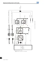
Figure 13.5 (h) to (j)
(cont.):
Details on the operation of the digital input functions
Time
Motor speed
24 V
24 V
Run/Stop
JOG Speed (P0122)
Deceleration ramp
24 V
DIx - JOG
General enable
Open
Open
Aceleration ramp
(h) JOG
With
Fault
24 V
General enable
Run/Stop
Time
24 V
Time
Time
24 V
Without fault
Reset
DIx - Reset
Open
Motor speed
Inverter
status
(*)
JOG+ (P0122), JOG- (P0123) Speed
Time
Time
Time
Time
Time
Time
(*)
The condition that caused the error persists.
24 V
Open
DIx - JOG ±
(j) RESET
Run/Stop
General enable
(i) JOG + and JOG -
Open
Open
Open
Summary of Contents for CFW700
Page 2: ......
Page 4: ......
Page 8: ...Summary...
Page 34: ...2 General Information 2 4 CFW700...
Page 38: ...3 About the CFW700 3 4 CFW700...
Page 56: ...7 Starting up and Settings 7 4 CFW700...
Page 58: ...8 Available Control Types 8 2 CFW700...
Page 78: ...10 VVW Control 10 8 CFW700...
Page 158: ...13 Digital and Analog Inputs and Outputs 13 28 CFW700...


