13
Digital and Analog Inputs and Outputs
13-4 | CFW700
P0235 – AI1 Filter
P0240 – AI2 Filter
Adjustable
Range:
0.00 to 16.00 s
Factory
Setting:
0.00 s
Properties:
Access groups
via HMI:
I/O
Description:
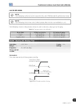
OFFSET
GAIN
FILTER
AI2’ - P0019
AI1 - P0231
AI2 - P0236
AI1 - P0232
AI2 - P0237
AI1 - P0234
AI2 - P0239
AI1 - P0235
AI2 - P0240
AI1’ - P0018
AIx'
Figure 13.2:
Analog input block diagram
The AIx’ internal value is the result of the following equation:
Alx' = Alx + OFFSET x 10 V x Gain
100
For instance: AIx = 5 V, OFFSET = -70 % and Gain = 1.000:
Alx' = 5 + (-70) x 10 V x 1 = -2 V
100
AIx’ = -2 V means that the motor will rotate in the reverse direction with a reference in module equal to 2 V,
provided that the AIx function is “Speed Reference”. For the AIx function “Maximum Torque Current”, negative
values are clipped at 0.0 %.
For the filter parameters (P0235 and P0240), the adjusted value corresponds to the RC constant used for
filtering the signal read at the input.
Summary of Contents for CFW700
Page 2: ......
Page 4: ......
Page 8: ...Summary...
Page 34: ...2 General Information 2 4 CFW700...
Page 38: ...3 About the CFW700 3 4 CFW700...
Page 56: ...7 Starting up and Settings 7 4 CFW700...
Page 58: ...8 Available Control Types 8 2 CFW700...
Page 78: ...10 VVW Control 10 8 CFW700...
Page 158: ...13 Digital and Analog Inputs and Outputs 13 28 CFW700...

