11
Vector Control
11-8 | CFW700
Settings for the torque control:
Torque limitation:
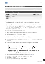
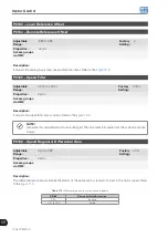
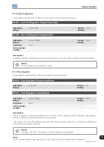
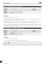
1. Via parameters P0169, P0170 (through the keypad (HMI), Serial or Fieldbus). Refer to
.
2. Through the analog inputs AI1 or AI2. Refer to
, option 2 (maximum torque current).
Speed reference:
3. Set the speed reference 10 %, or more, higher than the working speed. This assures that the speed regulator
output remains saturated at the maximum value allowed by the torque limit adjustment.
NOTE!
The torque limitation with the saturated speed regulator has also a protection (limitation) function. E.g.:
for a winder, when the material being wound brakes, the regulator leaves the saturated condition and
starts controlling the motor speed, which will be kept at the speed reference value.
11.6 OPTIMAL BRAKING
NOTE!
Only activated on the Vector with Encoder mode (P0202=5 or 4), when P0184=0, P0185 is smaller
than the standard value and P0404 < 21 (75 CV).
NOTE!
The occurrence of optimal braking may cause at the motor:
Increase of the vibration level.
Increase of the acoustic noise.
Increase of the temperature.
Verify the impact of those effects in the application before using the optimal braking.
It is a function that helps the motor controlled braking, eliminating in many cases the need of additional braking
IGBT and braking resistor.
The Optimal Braking makes it possible braking the motor with a higher torque than the one obtained with traditional
methods, as for instance, the braking by the injection of direct current (DC braking). In the DC braking case, only
the losses in the motor rotor are used to dissipate the energy stored as the mechanic load inertia, rejecting the
total friction losses. With the Optimal Braking, in the other hand, the total losses in the motor, as well as the total
inverter losses, are used. It is possible to get a braking torque roughly 5 times greater than with DC braking.
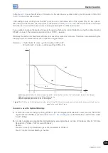
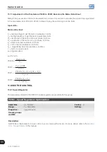
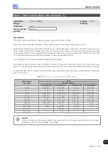
In the
the Torque x Speed curve of a typical 10 hp/7.5 kW IV pole motor is presented. The braking
torque obtained at the rated speed, for an inverter with a torque limit (P0169 and P0170) adjusted in a value equal
to the motor rated torque, is supplied by the TB1 point on the
. The value of TB1 is on the function of
the motor efficiency, and it is defined by the following expression, being despised the attrition losses:
TB1 = 1-
η
η
Where:
η
= motor efficiency.
Summary of Contents for CFW700
Page 2: ......
Page 4: ......
Page 8: ...Summary...
Page 34: ...2 General Information 2 4 CFW700...
Page 38: ...3 About the CFW700 3 4 CFW700...
Page 56: ...7 Starting up and Settings 7 4 CFW700...
Page 58: ...8 Available Control Types 8 2 CFW700...
Page 78: ...10 VVW Control 10 8 CFW700...
Page 158: ...13 Digital and Analog Inputs and Outputs 13 28 CFW700...


