19
Applications
19-6 | CFW700
c) Reading parameter 3 to show the motor speed:
- Set P0207 to 0002 which corresponds to the P0002 parameter of the CFW700.
- Set P0213 to 1800 rpm.
Operation setup
Check the status of the PID regulator application in parameter P1000. The PID regulator will be in operation if
P1000 value is 4. If P1000 value is 3, the PID regulator application is stopped and it is necessary to change the
command value of the SoftPLC at parameter P1001 to 1 (run application). Any value other than 3 or 4 indicates
that the applicative cannot go into operation. For more details, refer to the CFW700 SoftPLC manual.
1. Manual Operation (DIx is open):
keeping DIx open (Manual), check the process variable indication on the
keypad (P1012) based on an external measurement of the feedback signal value (transducer) at the AI2.
Then vary the speed reference (P0121) to get the desired process variable, only then, switch to automatic mode.
NOTE!
If the setpoint is defined by P1025, the CFW700 will automatically set P1025 value with P1012
instantaneous value when changing from manual to automatic mode (since P1026 = 1). In this case,
the switching from manual to automatic is smooth (no sudden change of speed).
2. Automatic Operation (DIx is closed):
close DIx and perform the dynamic adjustment of the PID regulator,
i.e., proportional gain (P1020), integral gain (P1021) and differential gain (P1022), checking whether the regulation
is being done correctly. In order to do that, it is necessary to compare the setpoint and process variable and
check if the values are close. See also how quickly the motor responds to fluctuations of the process variable.
It is important to know that the PID gains setup is a step that requires some attempts to reach the desired response
time. If the system responds rapidly and oscillates near the setpoint, then the proportional gain is too high. If the
system responds slow and takes time to reach the setpoint, then the proportional gain is too low and should be
increased. If the process variable does not reach the required value (setpoint), then the integral gain should be
adjusted.
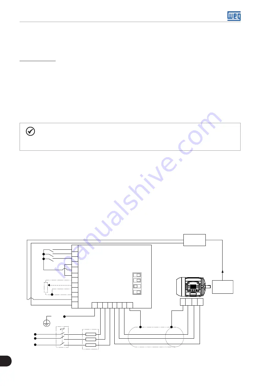
The following figure presents a simplified connection diagram of the CFW700 working as a PID regulator and also
the parameters setup of this sample.
37
39
40
35
34
36
21
22
23
24
25
26
DI1
DI3
DI4
COM
24 VDC
DGND
+REF
AI1+
AI1-
-REF
AI2+
AI2-
Setpoint
via keypad
CFW700
OFF ON
1
2
S1
XC1
PE R S T U V W PE
Shield
PE
U
V
W
DI1 - Run /Stop
DI3 - Manual / Automatic
DI4 - General Enable
Process
Pressure
Transducer
0-25 bar
4-20 mA
Setpoint
via AI1
≥5 kW
PE
R
S
T
Line
Isolating switch
Fuses
3
4
Figure 19.2:
Example of a CFW700 application as a PID regulator
Summary of Contents for CFW700
Page 2: ......
Page 4: ......
Page 8: ...Summary...
Page 34: ...2 General Information 2 4 CFW700...
Page 38: ...3 About the CFW700 3 4 CFW700...
Page 56: ...7 Starting up and Settings 7 4 CFW700...
Page 58: ...8 Available Control Types 8 2 CFW700...
Page 78: ...10 VVW Control 10 8 CFW700...
Page 158: ...13 Digital and Analog Inputs and Outputs 13 28 CFW700...


