


12
Functions Common to all the Control Modes
12-4 | CFW700
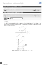
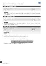
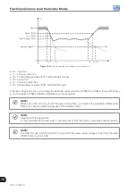
P0121 – Keypad Reference
Adjustable
Range:
0 to 18000 rpm
Factory
Setting:
90 rpm
Properties:
Access groups
via HMI:
Description:
When the
and
HMI keys are active (P0221 or P0222=0), this parameter sets the value of the motor
speed reference.
The value of P0121 will be kept with the last adjusted value when the inverter is disabled or powered off,
provided that the parameter P0120 is configured as Active (1).
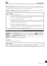
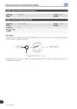
P0122 – JOG Speed Reference
Adjustable
Range:
0 to 18000 rpm
Factory
Setting:
150 rpm
(125 rpm)
Properties:
Access groups
via HMI:
Description:
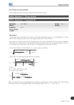
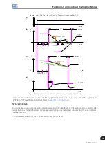
During the JOG command the motor accelerates up to the value defined in P0122 following the adjusted
acceleration ramp.
The source of the JOG command is defined in the parameters P0225 (Local Situation) or P0228 (Remote
Situation).
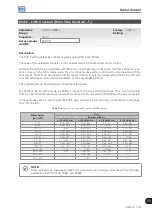
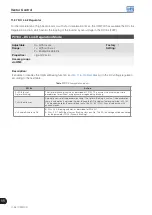
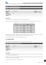
If the JOG command source has been defined for the digital inputs (DI1 to DI8), one of these inputs must be
programmed as presented in the
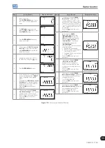
Table 12.1:
JOG command via digital input selection
Digital Input
Parameters
DI1
P0263 = 6 (JOG)
DI2
P0264 = 6 (JOG)
DI3
P0265 = 6 (JOG)
DI4
P0266 = 6 (JOG)
DI5
P0267 = 6 (JOG)
DI6
P0268 = 6 (JOG)
DI7
P0269 = 6 (JOG)
DI8
P0270 = 6 (JOG)
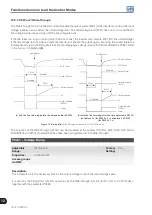
For more details refer to the
.
The speed direction is defined by the parameters P0223 or P0226.
The JOG command is effective only with the motor stopped.
For the JOG+ refer to the description below.
Summary of Contents for CFW700
Page 2: ......
Page 4: ......
Page 8: ...Summary...
Page 34: ...2 General Information 2 4 CFW700...
Page 38: ...3 About the CFW700 3 4 CFW700...
Page 56: ...7 Starting up and Settings 7 4 CFW700...
Page 58: ...8 Available Control Types 8 2 CFW700...
Page 78: ...10 VVW Control 10 8 CFW700...
Page 158: ...13 Digital and Analog Inputs and Outputs 13 28 CFW700...


