19
Applications
19-18 | CFW700
NOTE!
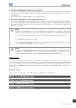
In case the electronic potentiometer application has been selected to operate in local mode and
DI1 (P0263) has been selected to accelerate or decelerate, the inverter can go to the “configuration
(CONF)” state and it will be necessary to change the default set of parameter P0227.
Operation Setup
Check the status of the electronic potentiometer application in parameter P1000. The electronic potentiometer will
be in operation if P1000 value is 4. If P1000 value is 3, the electronic potentiometer application is stopped and it
is necessary to change the command value of the SoftPLC in parameter P1001 to 1 (run application). Any value
other than 3 or 4 indicates that the applicative cannot go into operation. For more details, refer to the CFW700
SoftPLC manual.
19.3.3 Parameters
The parameters related to the Electronic Potentiometer Application (EP) are presented next in detail.
P0100 – Acceleration Time
P0101 – Deceleration Time
P0102 – Acceleration Time 2
P0103 – Deceleration Time 2
P0133 – Minimum Speed
P0134 – Maximum Speed
P0221 – LOC Reference Selection
P0222 – REM Reference Selection
P0263 – DI1 Function
P0264 – DI2 Function
P0265 – DI3 Function
P0266 – DI4 Function
P0267 – DI5 Function
P0268 – DI6 Function
P0269 – DI7 Function
P0270 – DI8 Function
P1000 – SoftPLC Status
Summary of Contents for CFW700
Page 2: ......
Page 4: ......
Page 8: ...Summary...
Page 34: ...2 General Information 2 4 CFW700...
Page 38: ...3 About the CFW700 3 4 CFW700...
Page 56: ...7 Starting up and Settings 7 4 CFW700...
Page 58: ...8 Available Control Types 8 2 CFW700...
Page 78: ...10 VVW Control 10 8 CFW700...
Page 158: ...13 Digital and Analog Inputs and Outputs 13 28 CFW700...


