11
Vector Control
11-26 | CFW700
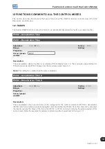
11.8.7 DC Link Regulator
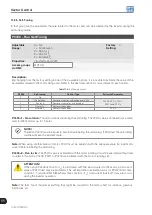
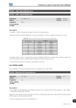
For the deceleration of high inertia loads or with short deceleration times, the CFW700 has available the DC Link
Regulation function, which avoids the tripping of the inverter by overvoltage in the DC link (F022).
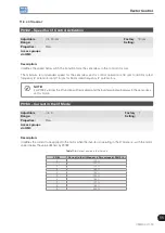
P0184 – DC Link Regulation Mode
Adjustable
Range:
0 = With losses
1 = Without losses
2 = Enable/Disable DIx
Factory
Setting:
1
Properties:
cfg and Vector
Access groups
via HMI:
Description:
It enables or disables the Optimal Braking function (
section 11.6 - Optimal Braking
) in the DC voltage regulation,
according to the next table.
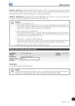
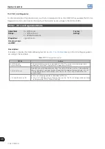
Table 11.7:
DC link regulation modes
P0184
Action
0 = With losses
(Optimal Braking)
The Optimal Braking is active as described at P0185. This assures the minimum possible
deceleration time without using dynamic or regenerative braking.
1 = Without losses
Automatic control of the deceleration ramp. The Optimal Braking is inactive. The deceleration
ramp is automatically adjusted in order to keep the DC link below the level adjusted in P0185.
This procedure avoids the overvoltage fault at the DC link (F022). It can also be used with
eccentric loads.
2 = Enable/Disable via DIx
DIx = 24 V: Braking actuates as described for P0184=1.
DIx = 0 V: The Without Losses Braking stays inactive. The DC link voltage will be controlled
by the parameter P0153 (Dynamic Braking).
Summary of Contents for CFW700
Page 2: ......
Page 4: ......
Page 8: ...Summary...
Page 34: ...2 General Information 2 4 CFW700...
Page 38: ...3 About the CFW700 3 4 CFW700...
Page 56: ...7 Starting up and Settings 7 4 CFW700...
Page 58: ...8 Available Control Types 8 2 CFW700...
Page 78: ...10 VVW Control 10 8 CFW700...
Page 158: ...13 Digital and Analog Inputs and Outputs 13 28 CFW700...

