0
Quick Parameter Reference, Faults and Alarms
CFW700 | 0-19
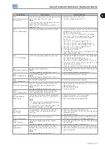
Fault/Alarm
Description
Possible Causes
F150:
Motor Overspeed
Overspeed fault.
It trips when the actual speed exceeds the value
of P0134 x (100 % + P0132)
100%
for more than 20 ms.
Wrong settings of P0161 and/or P0162.
Problem with a hoist-type load.
F151:
FLASH Memory Module
Fault
FLASH Memory Module (MMF-01) fault.
Defective FLASH memory module.
Check the connection of the FLASH memory module.
A152:
High Internal Air
Temperature
This alarm indicates that the internal air
temperature is too high.
Note:
It can be disabled by setting P0353 = 1 or 3.
High surrounding air temperature (>50 °C (122 °F)) and
high output current.
Defective internal fan (if existent).
High temperature (> 45 ºC) inside the cabinet.
F153:
Internal Air
Overtemperature
It indicates internal air overtemperature fault.
High surrounding air temperature (>50 °C (122 °F)) and
high output current.
Defective internal fan (if existent).
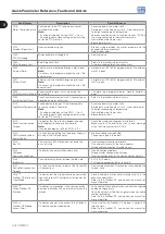
F156:
Undertemperature
The temperature sensors located in the IGBTs or
in the rectifier detected a low temperature, below
-30 °C ( -22 °F), fault.
Surrounding air temperature ≤ -30 °C (-22 °F).
F157:
Parameter Table Data
Loss
There was a problem during the initialization,
during the parameter table loading routine. Some
recent parameter modifications may have been
lost.
The control was switched off very fast while a parameter
was being modified.
F158:
Parameter Table Fault
There was a problem during the initialization,
during the parameter table loading routine. All
the parameters were lost and the factory settings
were loaded.
Firmware updating fault.
Defective control board.
F160:
Safety Stop Relays
Safety stop relay fault.
One of the relays is defective or it does not have +24 V
applied to its coil.
A163:
AI1 Broken Cable
It indicates that the AI1 current (4-20 mA or
20-4 mA) reference is out of the 4 to 20 mA range.
Broken AI1 cable.
Bad contact at the connection of the signal to the
terminal strip.
A164:
AI2 Broken Cable
It indicates that the AI2 current (4-20 mA or
20-4 mA) reference is out of the 4 to 20 mA range.
Broken AI2 cable.
Bad contact at the connection of the signal to the
terminal strip.
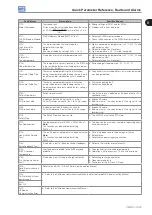
A170:
Safety Stop
The Safety Stop function is active.
The CFW700 went to the STO state.
A177:
Fan Replacement
Fan replacement alarm (P0045 > 50000 hours).
Note:
This function can be disabled by setting
P0354 = 0.
The heatsink fan maximum number of operating hours
has been reached.
F179:
Heatsink Fan Speed
Fault
This fault indicates a problem with the heatsink fan.
Note:
This function can be disabled by setting
P0354 = 0.
Dirt on the blades and in the bearings of the fan.
Defective fan.
Defective fan power supply connection.
F182:
Pulse Feedback Fault
It indicates a fault in the output pulses feedback.
Defect in the inverter internal circuitry.
F183:
IGBT Ov
Temperature
Overtemperature related to the IGBT overload
protection.
Too high inverter surrounding temperature.
Operation with frequencies < 10 kHz with overload.
F185:
Pre-Charge Contactor
Fault
It indicates a fault at the pre-charge contactor.
Defective pre-charge contactor.
Open command fuse.
Phase loss at the L1/R or L2/S input.
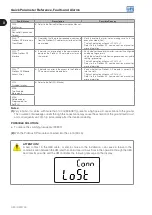
F228:
Serial Communication
Timeout
Refer to the RS-232 / RS-485 Serial Communication Manual.
F233:
CAN interface without
power supply
Refer to the CANopen Communication Manual and/or the DeviceNet Communication Manual.
F234:
Bus Off
F235:
CANopen
Communication Error
Refer to the CANopen Communication Manual.
Summary of Contents for CFW700
Page 2: ......
Page 4: ......
Page 8: ...Summary...
Page 34: ...2 General Information 2 4 CFW700...
Page 38: ...3 About the CFW700 3 4 CFW700...
Page 56: ...7 Starting up and Settings 7 4 CFW700...
Page 58: ...8 Available Control Types 8 2 CFW700...
Page 78: ...10 VVW Control 10 8 CFW700...
Page 158: ...13 Digital and Analog Inputs and Outputs 13 28 CFW700...


