


0
Quick Parameter Reference, Faults and Alarms
CFW700 | 0-3
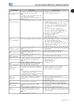
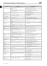
Param.
Description
Adjustable Range
Factory Setting
User
Setting
Propr.
Grorps
Pag.
P0135
Maximum Output Current
0.2 to 2 x I
nom-HD
1.5 x I
nom-HD
V/f and
V V W
BASIC
9-7
P0136
Manual Torque Boost
0 to 9
1
V/f
BASIC
9-2
P0137
Automatic Torque Boost
0.00 to 1.00
0.00
V/f
9-2
P0138
Slip Compensation
-10.0 to 10.0 %
0.0 %
V/f
9-3
P0139
Output Current Filter
0.0 to 16.0 s
0.2 s
V/f and VVW
9-4
P0142
Maximum Output Voltage
0.0 to 100.0 %
100.0 %
cfg and Adj
9-5
P0143
Intermediate Output Voltage 0.0 to 100.0 %
50.0 %
cfg and Adj
9-5
P0144
3 Hz Output Voltage
0.0 to 100.0 %
8.0 %
cfg and Adj
9-5
P0145
Field Weakening Speed
0 to 18000 rpm
1800 rpm
cfg and Adj
9-6
P0146
Intermediate Speed
0 to 18000 rpm
900 rpm
cfg and Adj
9-6
P0150
V/f DC Regulation Type
0 = Ramp Hold
1 = Ramp Acceleration
0 = Ramp Hold
cfg, V/f
and V V W
9-11
P0151
V/f DC Regulation Level
339 to 800 V
800 V
V/f and VVW
9-11
P0152
V/f DC Regulation P Gain
0.00 to 9.99
1.50
V/f and VVW
9-12
P0153
Dynamic Braking Level
339 to 800 V
748 V
14-1
P0156
100 % Speed Overload
Current
0.1 to 1.5 x I
nom-ND
1.05 x I
nom-ND
15-4
P0157
50 % Speed Overload
Current
0.1 to 1.5 x I
nom-ND
0.9 x I
nom-ND
15-4
P0158
5 % Speed Overload Current 0.1 to 1.5 x I
nom-ND
0.65 x I
nom-ND
15-4
P0159
Motor Tripping Class
0 = Class 5
1 = Class 10
2 = Class 15
3 = Class 20
4 = Class 25
5 = Class 30
6 = Class 35
7 = Class 40
8 = Class 45
1 = Class 10
cfg
15-5
P0160
Speed Regulation
Optimization
0 = Normal
1 = Saturated
0 = Normal
cfg and
Vector
11-14
P0161
Speed Proportional Gain
0.0 to 63.9
7.4
Vector
11-15
P0162
Speed Integral Gain
0.000 to 9.999
0.023
Vector
11-15
P0163
LOC Reference Offset
-999 to 999
0
Vector
11-16
P0164
REM Reference Offset
-999 to 999
0
Vector
11-16
P0165
Speed Filter
0.012 to 1.000 s
0.012 s
Vector
11-16
P0166
Speed Differential Gain
0.00 to 7.99
0.00
Vector
11-16
P0167
Current Proportional Gain
0.00 to 1.99
0.50
Vector
11-17
P0168
Current Integral Gain
0.000 to 1.999
0.010
Vector
11-17
P0169
M Torque Current
0.0 to 350.0 %
125.0 %
Vector
11-25
P0170
Maximum - Torque Current
0.0 to 350.0 %
125.0 %
Vector
11-25
P0175
Flux Proportional Gain
0.0 to 31.9
2.0
Vector
11-17
P0176
Flux Integral Gain
0.000 to 9.999
0.020
Vector
11-17
P0178
Rated Flux
0 to 120 %
100 %
Vector
11-18
P0179
Maximum Flux
0 to 120 %
120 %
Vector
11-18
P0182
Speed for I/f Activation
0 to 90 rpm
18 rpm
Sless
11-19
P0183
Current in I/f Mode
0 to 9
1
Sless
11-19
P0184
DC Link Regulation Mode
0 = With losses
1 = Without losses
2 = Enable/Disable DIx
1 = Without losses
cfg and
Vector
11-26
P0185
DC Link Regulation Level
339 to 800 V
800 V
Vector
11-27
P0186
DC Link Proportional Gain
0.0 to 63.9
18.0
Vector
11-27
P0187
DC Link Integral Gain
0.000 to 9.999
0.002
Vector
11-27
P0190
Maximum Output Voltage
0 to 480 V
440 V
Vector
11-18
P0191
Encoder Zero Search
0 = Inactive
1 = Active
0 = Inactive
12-22
P0192
Encoder Zero Search Status 0 = Inactive
1 = Finished
0 = Inactive
ro
READ
12-22
Summary of Contents for CFW700
Page 2: ......
Page 4: ......
Page 8: ...Summary...
Page 34: ...2 General Information 2 4 CFW700...
Page 38: ...3 About the CFW700 3 4 CFW700...
Page 56: ...7 Starting up and Settings 7 4 CFW700...
Page 58: ...8 Available Control Types 8 2 CFW700...
Page 78: ...10 VVW Control 10 8 CFW700...
Page 158: ...13 Digital and Analog Inputs and Outputs 13 28 CFW700...


