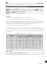


Functions Common to all the Control Modes
12
CFW700 | 12-7
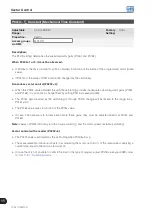
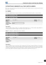
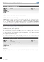
12.4 ZERO SPEED LOGIC
This function allows the configuration of a speed in which the inverter will enter a stop condition (general disable).
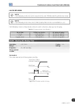
P0217 – Zero Speed Disable
Adjustable
Range:
0 = Inactive
1 = Active
Factory
Setting:
0
Properties:
cfg
Access groups
via HMI:
Description:
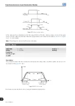
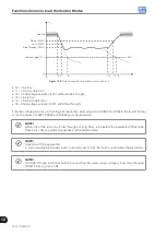
When active, it disables the inverter after the speed reference (N*) and the actual speed (N) become lower than
the value adjusted in the parameter P0291.
The inverter is enabled again when one of the conditions defined by the parameter P0218 is satisfied.
DANGER!
Be careful when approaching the motor while it is in the disable condition. It may get back to operation
at any moment because of the process conditions. In case you want to handle or perform any type
of maintenance, remove power from the inverter.
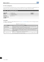
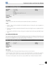
P0218 – Condition to Leave the Zero Speed Disable
Adjustable
Range:
0 = Reference or Speed
1 = Reference
Factory
Setting:
0
Properties:
Access groups
via HMI:
Description:
It specifies if the condition to leave the zero speed disable will be only the speed reference or also the actual
speed.
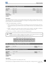
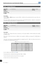
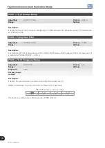
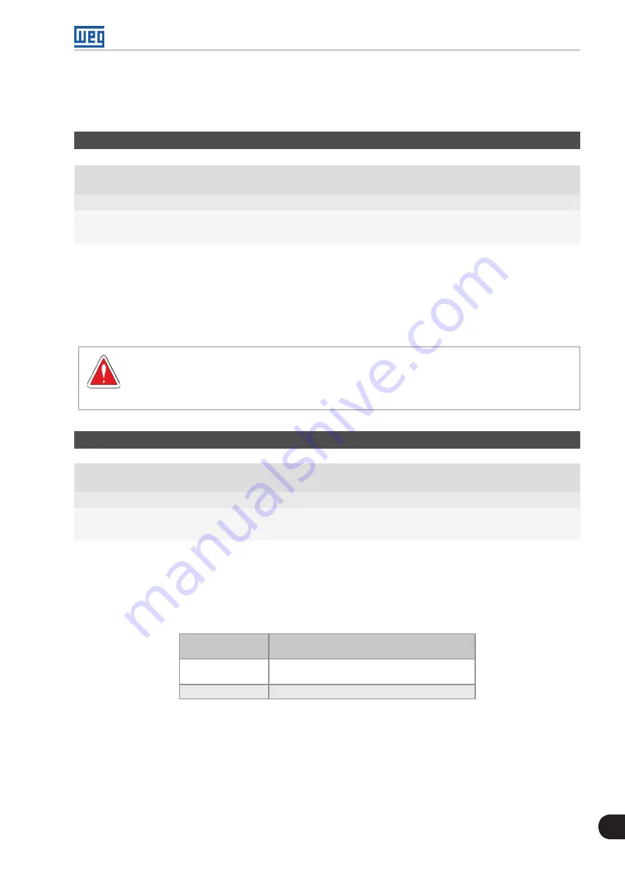
Table 12.3:
Condition to leave the N=0 disable
P0218
(P0217 = 1)
Inverter Leaves the Condition of Disable by N=0
0
P0001 (N*) > P0291 or
P0002 (N) > P0291
1
P0001 (N*) > P0291
In order the inverter can exit the blocked condition when the PID Regulator application is active and in Auto
mode, besides the programming at P0218, it is necessary that the PID error (the difference between the
setpoint and the process variable) is greater than the value set in P1028. Refer to the
for more details.
Summary of Contents for CFW700
Page 2: ......
Page 4: ......
Page 8: ...Summary...
Page 34: ...2 General Information 2 4 CFW700...
Page 38: ...3 About the CFW700 3 4 CFW700...
Page 56: ...7 Starting up and Settings 7 4 CFW700...
Page 58: ...8 Available Control Types 8 2 CFW700...
Page 78: ...10 VVW Control 10 8 CFW700...
Page 158: ...13 Digital and Analog Inputs and Outputs 13 28 CFW700...


