


Digital and Analog Inputs and Outputs
13
CFW700 | 13-11
DC Link Regulation:
It must be used when P0184=2. For more details, refer to this parameter description
in
item 11.8.7 - DC Link Regulator
, of this manual.
JOG+ and JOG-:
Those are functions valid only for P0202=5 or 4.
Disables Flying-Start:
It is valid for P0202≠5. By ap24 V to the digital input programmed for this
purpose, the Flying-Start function is disabled. By applying 0 V, the Flying-Start function is enabled again,
provided that P0320 be equal to 1 or 2. Refer to the
section 12.5 - Flying Start/Ride-Through
Load User 1:
This function allows the selection of the user memory 1, in a similar process than P0204=7,
with the difference that the user memory is loaded from a transition of the DIx programmed for this function.
When the state of the DIx changes from low level to high level (transition from 0 V to 24 V), the user memory 1
is loaded, provided that the contents of the inverter actual parameters had been previously transferred to the
parameter memory 1 (P0204=9).
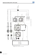
Inverter
Parameters
User 1
User 2
P0204=10
P0204=9
P0263
to
P0270
(DIx)=18
DIx=0 V
P0263 to P0270 (DIx)=19
DIx=24 V
DIx=0 V
DIx=24 V
Figure 13.4:
Details on the working of the Load User 1 or 2 function
Load User 2:
This function allows the selection of the user memory 2, in a similar process than P0204=8,
with the difference that the user memory is loaded from a transition of the DIx programmed for this function.
When the state of the DIx changes from low level to high level (transition from 0 V to 24 V), the user memory 2
is loaded, provided that the contents of the inverter actual parameters had been previously transferred to the
parameter memory 2 (P0204=10).
NOTES!
Make sure that when using those functions the parameter sets (user memory 1, 2) be totally compatible
with the application (motors, Run/Stop commands, etc.).
It will not be possible to load the user memory with the inverter enabled.
If two parameter sets from different motors were saved in the user memories 1 and 2, the correct
current values must be adjusted at the parameters P0156, P0157 and P0158 for each user memory.
Parametrization Blocking:
When this function is programmed and the digital input is with +24 V, parameter
changes will not be allowed, regardless of the values set at P0000 and P0200. When the DIx input is with 0 V,
the parameter changes will be conditioned to the P0000 and P0200 settings.
No External Alarm:
This function will indicate “External Alarm” (A090) on the keypad (HMI) display when
the programmed digital input is open (0 V). If +24 V is applied to the input, the alarm message will disappear
automatically from the keypad (HMI) display. The motor keeps working normally, regardless of the state of
that input.
Application Function:
Sets the input to be used by the applications. For more details, refer to
.
Summary of Contents for CFW700
Page 2: ......
Page 4: ......
Page 8: ...Summary...
Page 34: ...2 General Information 2 4 CFW700...
Page 38: ...3 About the CFW700 3 4 CFW700...
Page 56: ...7 Starting up and Settings 7 4 CFW700...
Page 58: ...8 Available Control Types 8 2 CFW700...
Page 78: ...10 VVW Control 10 8 CFW700...
Page 158: ...13 Digital and Analog Inputs and Outputs 13 28 CFW700...


