11
Vector Control
11-10 | CFW700
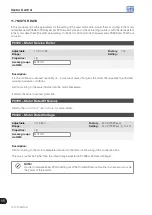
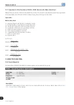
11.7 MOTOR DATA
In this group are listed the parameters for the setting of the used motor data. Adjust them according to the motor
nameplate data (P0398 to P0406), except P0405, and by means of the self-tuning routine or with the data existent
in the motor data sheet (the other parameters). In the Vector Control mode the parameters P0399 and P0407 are
not used.
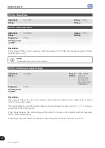
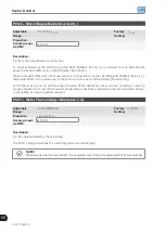
P0398 – Motor Service Factor
Adjustable
Range:
1.00 to 1.50
Factory
Setting:
1.00
Properties:
cfg
Access groups
via HMI:
MOTOR
Description:
It is the continuous overload capability, i.e., a reserve of power that gives the motor the capability to withstand
working in adverse conditions.
Set it according to the value informed on the motor nameplate.
It affects the motor overload protection.
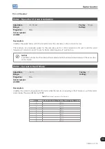
P0399 – Motor Rated Efficiency
Refer to the
, for more details.
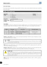
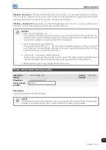
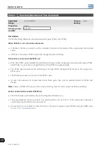
P0400 – Motor Rated Voltage
Adjustable
Range:
0 to 480 V
Factory
Setting:
220 V (P0296=0)
440 V (P0296=1, 2, 3 or 4)
Properties:
cfg
Access groups
via HMI:
MOTOR
Description:
Set it according to the motor nameplate data and to the motor cable wiring in the connection box.
This value cannot be higher than the rated voltage adjusted in P0296 (Line Rated Voltage).
NOTE!
In order to validate a new P0400 setting out of the Oriented Start-up Routine it is necessary to cycle
the power of the inverter.
Summary of Contents for CFW700
Page 2: ......
Page 4: ......
Page 8: ...Summary...
Page 34: ...2 General Information 2 4 CFW700...
Page 38: ...3 About the CFW700 3 4 CFW700...
Page 56: ...7 Starting up and Settings 7 4 CFW700...
Page 58: ...8 Available Control Types 8 2 CFW700...
Page 78: ...10 VVW Control 10 8 CFW700...
Page 158: ...13 Digital and Analog Inputs and Outputs 13 28 CFW700...


