

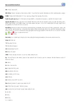

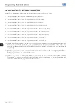
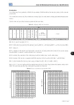
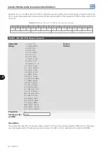

3
About the CFW700
CFW700 | 3-3
6
3
2
9
5
4
7
8
1
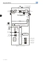
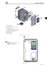
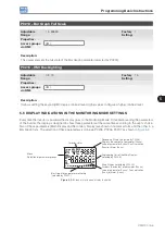
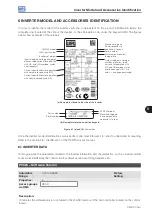
1 - Mounting supports
(for surface mounting)
2 - Back side of the inverter (outside for flange
mounting)
3 - Fan with fixing support
4 - Control accessory module (refer to section 7.2 -
Accessories, of the CFW700 user's manual)
5 - FLASH memory module (not included)
6 - Front cover (sizes A, B and C)
7 - Keypad (HMI)
8 - Status LED (STATUS)
9 - CC700 control board
Figure 3.2:
CFW700 main components
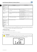
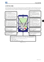
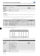
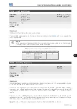
Status LED
Green
: Normal operation without fault or alarm
Yellow
: In the alarm condition
Blinking red
: In the fault condition
1
1
Figure 3.3:
LEDs
Summary of Contents for CFW700
Page 2: ......
Page 4: ......
Page 8: ...Summary...
Page 34: ...2 General Information 2 4 CFW700...
Page 38: ...3 About the CFW700 3 4 CFW700...
Page 56: ...7 Starting up and Settings 7 4 CFW700...
Page 58: ...8 Available Control Types 8 2 CFW700...
Page 78: ...10 VVW Control 10 8 CFW700...
Page 158: ...13 Digital and Analog Inputs and Outputs 13 28 CFW700...


